
Lecture I. Tractors and automobiles, agricultural requirements for tractors and automobiles. Great encyclopedia of oil and gas

During the movement of the tractor and the car, the external resistance is constantly changing within wide limits. This is due to fluctuations in the specific resistance of the soil and the load of the working bodies of the machines, changes in the rolling resistance of the wheels and their adhesion to the ground or the road, additional rises or inclines. Accordingly, it is required to change the torque supplied to the drive wheels (sprocket), both to overcome the increased resistances, and to more fully use the engine power, to obtain high performance with the lowest fuel consumption. In addition, depending on the conditions, it is necessary to stop the tractor or the car or change the direction of their movement. Therefore, a tractor and a car are used in a number of mechanisms and assemblies, called transmissions.
The transmission is used to transmit the engine torque to the driving wheels of the tractor (car), and is also used to transfer part of the engine power of the machine aggregated with the tractor. With the help of the transmission, you can change the torque and speed of the driving wheels in terms of value and direction.
By way of changing the torquetransmissions are divided into step, steplessand combined.
Stepped change torque with an interval multiple of the gear ratio (gear). They consist of gears, joints and couplings of various types. Stepless provide continuous and automatic change of torque depending on external resistances. For continuously variable transmissions include friction (mechanical), electrical and hydraulic. Combined transmissions are a combination of stepped mechanical transmissions with continuously variable transmissions.
By the principle of actiontransmissions can be mechanical,electric, hydraulicand combined (hydromechanicalcue, electromechanicaletc.).
Mechanical transmission, widely used in modern tractors and cars, includes a clutch, intermediate connection, gearbox, final drive, differential, final gears (Fig. 4.1, but).
R  is 4.1. Tractor transmissions scheme:
a - wheeled with rear axle; 6-wheeled with front and rear axles; in - tracked; 1 - clutch; 2-intermediate clutch; 3 - gearbox; 4- main gear; 5-differential; 6- final transfer; 7- transfer case; 8-driveline; 9- rotation mechanisms; 10- special mechanism
In wheeled tractors with both driving axles (type MTZ-82), an additional transfer box, cardan transmission, as well as the main gear, differential and final drive of the front axle are additionally installed (Fig. 4.1, b).
Tracked tractors are equipped with turning mechanisms (Fig. 4.1, at)and, if necessary, a torque magnifier, a creeper, etc.
The change in the gear ratio of a mechanical manual transmission occurs in the gearbox when gears with different numbers of teeth are engaged in the gearing. Stepped gearboxes have sets of gears, which allow getting in modern cars 4-5 steps, and in tractors - up to 24 or more with different gear ratios. Mechanical transmissions have high efficiency and relatively low cost. However, in them the rotational speed is regulated in steps.
An electric transmission consists of a DC generator that receives rotation from an internal combustion engine. The electrical energy produced by the generator goes to the traction motors, which are installed in the driving wheels or sprockets, and drives them into rotation. The advantages of this transmission are ease of energy transfer and infinitely variable control, drawbacks are low efficiency, a large mass of aggregates, and a relatively high cost.
Hydraulic transmission as the main element has a hydraulic transmission. Hydraulic transmission is understood as a device designed to transfer mechanical energy through a fluid.
There are hydrostatic (volumetric) and hydrodynamic transmission. Hydrostatic transmission with hydrostatic transmission consists of a pump, switchgear, hydraulic lines and motors located in the drive wheels. Oil under the working pressure from the pump, driven by the engine, enters the switchgear, from which it is sent to the driving motors of the driving wheels of the tractor or the car. The disadvantages of this transmission include low efficiency, a large mass of aggregates, the need for high precision manufacturing and ensuring high tightness.
Hydromechanical transmission consists of a mechanical transmission and hydrodynamic transmission: hydraulic clutch or torque converter. Hydrodynamic transmission is based on the use of the kinetic energy of a liquid, i.e. the transfer of energy due to the dynamic pressure of a liquid. The advantages of the transmission: infinitely variable speed control within the limits of the steps, less dynamic loads on the details of the transmission, better acceleration and greater smoothness of movement. The disadvantages of such a transmission should include a relatively low efficiency, design complexity and a large mass.
Electromechanical transmission has an electrical transmission, consisting of a generator and a DC motor. Electric transmission, like hydrodynamic, automatically and continuously changes the torque and speed of movement in accordance with the resistance to movement. However, this transmission is characterized by low efficiency, increased mass and high cost.
Lecture I. TRACTORS AND CARS APPLIED IN AGRICULTUREREQUIREMENTS FOR TRACTORS AND CARS
Tractors and automobiles are complex mobile energy and vehicles used for complex mechanization and automation of agricultural production, as well as for the transportation of agricultural goods and passengers.
Tractors and cars must meet specific performance requirements based on scientifically based properties and performance. These requirements include, first of all, ensuring high productivity and efficiency, the implementation of the entire complex of agricultural work with high quality, in the best agronomic terms. Of great importance are the requirements of an agro-ecological nature, associated with the pollution of the atmosphere by harmful components contained in the exhaust gases of engines and the effect of the running gear of these machines on the soil. The running gear compresses and rubs the soil, which negatively affects its fertility and crop yields. Therefore, reducing the negative impact of tractors and cars on the soil is one of the most important operational requirements.
The performance of a tractor operating in an aggregate with agricultural machines depends on their working width, the power of the tractor engine, the traction resistance of the machines, the average speed of movement of the machine-tractor aggregate (MTA) and other factors. In this regard, the performance of the unit is determined by the energy saturation and traction characteristics of tractors. In addition, productivity depends on the operator’s fatigue degree, which, in turn, depends on the tractor’s smoothness, cabin safety from noise, gases, dust and ambient temperature, ease of operation and maintenance, cabin visibility, i.e. ergonomic properties of tractors, characterizing the working conditions of the tractor driver and maintenance personnel. The integral indicator of the productivity and efficiency of the tractor - the cost of agricultural work.
The performance of the car is determined by the mass of the transported cargo or the number of passengers, as well as the average speed. In this regard, it depends on the engine power,
Patency, smoothness and reliability of the car, the condition of the road surface, ease of management and other factors that characterize the working conditions of the driver. The integral indicator of the performance and efficiency of the car - the cost of transportation. For transporting agricultural goods, in addition to automobiles, tractors, especially wheeled ones, are used in the aggregate with trailers and semi-trailers. So, up to 50% of the total working time of wheeled tractors is spent on transport work. In this regard, the same requirements are imposed on tractors as on automobiles, for example, ensuring traffic safety and good smoothness at high speeds, the availability of automotive-type signaling systems, etc.
Requirements aimed at ensuring high productivity should be met together with agrotechnical requirements. These requirements are interrelated. Agrotechnical requirements for agricultural tractors: ensuring the patency of machines on any surface and in between rows of row crops; compliance with the required ranges of traction effort and speed, as well as maneuverability; minimum harmful effects of the chassis on the soil; high-quality execution of technological processes.
The quantitative characteristics of the main agrotechnical requirements are as follows:
Slipping of tracked tractor and wheeled engines with two and four drive wheels should be no more than 3, 14 and 16% respectively;
soil thrust pressure is allowed not more than 45 kPa for tracked vehicles and 110 kPa for wheeled vehicles;
ground clearance (the smallest vertical distance from the supporting surface to the tractor structural elements) must be at least 36 cm for tracked tractors and 47 cm under the rear axle for universal tilled tractors;
The agrotechnical clearance (vertical distance from the supporting surface to the least distant structural elements of the tractor over a row of cultivated plants) should be 40 ... 55 cm for main low stem crops (potatoes, beets, etc.) and 65 ... 75 cm for high stem crops (corn, sunflower, etc.);
the protection zone (the horizontal distance from the middle of the row to the edge of the wheel or tractor track, depending on the phase of plant development and the type of processing) when cultivating row crops should be 12 ... 15 cm (minimum);
gauge and overall dimensions of the tractor should provide mutual constructive coordination with the aggregated agricultural machines, as well as the ability to work universal-tilled tractors in between rows 45, 60, 70, 90 cm and in transport operations;
7) the smallest turning radius of the tractor should be 3 ... 4.5 m for universal wheeled tractors, 6.5 ... 7.5 m for general purpose wheeled tractors and 2 ... 2.5 m for tracked tractors .
CLASSIFICATION AND GENERAL DEVICE OF TRACTORS AND CARS
CLASSIFICATION OF TRACTORS
A tractor is a wheeled or tracked self-propelled vehicle designed to move trailed or mounted agricultural and road machines, as well as trailers. The working bodies and mechanisms of these machines can be driven and the action from the tractor engine through the power take-off shaft (NOM).
Tractors are used in agricultural, construction and road works, in forest work, in the drainage and irrigation of land, for the transportation of goods.
In order to carry out a large number of works of diverse nature, the national economy needs tractors of various types. The combination of models of tractors produced to meet the needs of the national economy, forms a type of tractors. Classification indicator type - traction class. The modern type of tractors consists of traction classes, each of which differs from another value of the nominal tractive effort. Such an effort can be realized by the tractor on the stubble (black soil or loam) of normal humidity and density, provided that the skidding does not exceed certain values.
In agricultural production, tractors of nine classes with a pulling force of 2; 6; 9; 14:20; thirty; 40; 50; 60 kN.
Each class contains one basic (basic) model of the tractor and several of its varieties (modifications). The latter are used to perform special agricultural operations. By design, the modification is a modified model of the base tractor, preserving its main units, i.e. having a high degree of uniformity (unification).
Agricultural tractors are classified according to the following criteria:
The purpose - general purpose, universal-tilled, specialized;
By chassis type - wheeled and tracked;
By type of the core - frame, semi-frame, frameless.
CLASSIFICATION OF CARS
Cars are classified according to the following main features. To destination distinguish passenger, cargo and special cars.
Passenger cars that carry no more than eight people, taking into account the driver, are called passenger cars, and for transporting more than eight people - buses. Cars produced with closed and opening bodies. Buses are divided at the place of their operation on urban, intercity and tourist.
Trucks are distinguished by capacity, i.e. on the mass of cargo that can be transported in the back. It is indicated in the technical characteristics of a car for paved roads. Depending on the nature of the use of vehicles, there may be general-purpose vehicles with a non-tilting flatbed, specialized (dump trucks, tanks, container carriers, etc.) and tractors (for permanent work with trailers and semi-trailers). Tow trucks and general purpose coupled to a trailer (semi-trailer) are called road trains.
On cars install diesel, carburetor, gas and electric engines.
According to their fitness for road conditions, vehicles are distinguished for road (normal) terrain (for working mainly on paved and dry unpaved roads) and all-terrain (for driving on bad roads and in off-road conditions).
Road vehicles have a drive on one axle (two driving wheels), and a cross-country drive - on two axles (four driving wheels) or, if there are several axles, on three or four axles (six or eight driving wheels).
All cars are conventionally denoted by the wheel formula, where the first digit is the total number of wheels, and the second is the number of driving wheels, and dual driving wheels are counted as one wheel. For example, a 4x2 car has four wheels, of which two are driving, and a 4x4 type is also four wheels, all driving.
GENERAL DEVICE OF TRACTORS AND CARS
The main parts of the tractor and car: engine, transmission, chassis, control mechanisms, working and auxiliary equipment.
Crawler.The arrangement of the main parts and assembly units of the crawler tractor is shown in Figure 1.1.
Engine 1 converts chemical energy of fuel and atmospheric air into rotational motion and transfers it to consumers - driving wheels and PTO.
The transmission transforms the rotational motion, distributes it and carries it to the drive wheels (sprockets). Transmission consists of clutch 9, connecting shaft 8, gear boxes 7 turning mechanisms 5 the main 12 and end 6 gears.
The undercarriage integrates all the assembly units into one unit and serves to move the tractor along the supporting surface. The chassis consists of a frame (frame), suspension and propulsion unit, which includes driving wheels 4 (asterisks), guide wheels 11 supporting rollers and track chains 10. The propeller interacts with the supporting surface (soil) and converts the rotational movement of the transmission brought in by the tractor into translational motion.
Fig. 1.1. The layout of the main parts, mechanisms and parts of the tracked
tractor:
1- engine; 2-hinged hydraulic system; 3- tow hitch; 4 - drive wheel; 5-planetary gear; 6-final gear; 7-gearbox; 8-connecting cash; 9-clutch; 10- track chain; 11 -the steering wheel; 12 - main gear
The control mechanisms, acting on the undercarriage, change the trajectory of the tractor, stop and keep it motionless.
The working equipment of the tractor consists of a hinge mechanism 2 hydraulically trailed 3, PTO and drive pulley. The hinged system is designed to mount the mounted machines on the tractor and control their work. With the help of the hitch tow various towed machines and vehicles. PTO is used to actuate the working bodies of aggregated machines.
Auxiliary equipment of the tractor is a cab with a sprung seat, a bonnet, lighting and alarm devices, heating and ventilation systems, a compressor, etc.
Wheel tractor.The purpose of the wheel factor components (Fig. 1.2) is the same as that of the caterpillar.
The chassis and control mechanisms of the wheeled tractor consist of a wreck, front axle 2 leading 5 and managed 1 wheels, steering. Between the main 8 and ultimate 6 gear set differential 7 .
Car.The main parts of the car (Fig. 1.3) - the engine, chassis and body. The schematic diagram of the location of the main parts and mechanisms of the car differs little from the scheme of their location at the wheel tractor.
The chassis of the car consists of a transmission, running gear and control mechanisms. On the chassis set the body to accommodate passengers or cargo.
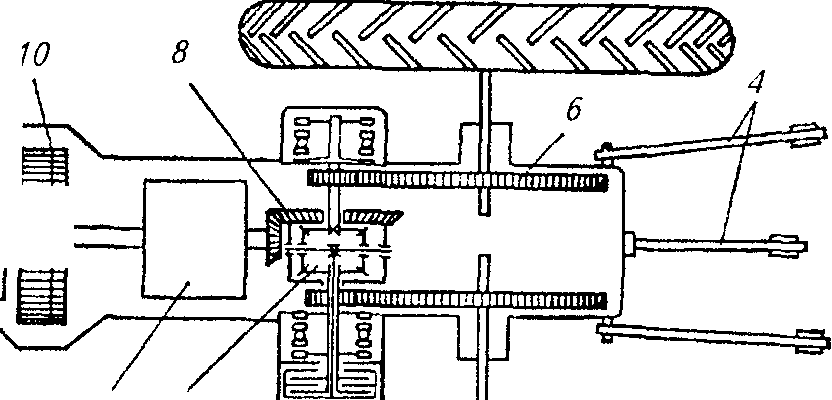 Fig. 1.2. The layout of the main parts, mechanisms and parts of the wheel
tractor:
/ - steered wheel; 2 - front axle. J - engine; 4 - chechenpchm hitch: /\u003e - drive wheel; 6- final transmission; 7 - differential: S ~ main gear; U - gearbox; 10- curing

Fig. 1.3. The location of the main mechanisms of the car:
1
-the steering wheel; 2-front suspension; 3 -
clutch; 4 -
transmission; five-
cardan transmission; 6-
main gear; 7-differential; 8
-rear suspension: 9-
drive wheel; 10 -
frame; 11
- steering; 12-
engine
Ancillary equipment of cars is a traction coupling device, a winch, heating and ventilation systems, a compressor, etc.
The layout of front-wheel-drive passenger cars differs from the classic one (see Fig. 1.3) in that the engine is located across the body and the front wheels are leading. This allowed to reduce the weight of the car, more efficiently use its space, increase stability and throughput.
CLASSIFICATION, MAIN MECHANISMS AND ENGINE SYSTEMS
On modern tractors and automobiles, piston internal combustion engines are mainly used. Inside these engines a combustible mixture burns (a mixture of fuel and air in certain proportions and quantities). Part of the heat released during this process is converted into mechanical work.
Engine classification.Piston engines are classified by the following features:
According to the method of ignition of a combustible mixture - from compression (diesel engines) and from an electric spark;
The method of mixture formation - with external (carburetor and gas) and internal (diesel) mixture formation;
The method of implementation of the working cycle - four and two-stroke;
The type of fuel used - working on liquid (gasoline or diesel fuel), gaseous (compressed or liquefied gas) fuel and multi-fuel;
The number of cylinders - single and multi-cylinder (two-, three-, four-, six-cylinder, etc.);
The location of the cylinders is single or linear (the cylinders are arranged in one row), and two-row or V-shaped (one row of cylinders is placed at an angle to the other).
Four-stroke multi-cylinder diesel engines are used on tractors and heavy-duty automobiles, and four-stroke multi-cylinder carburetor and diesel engines, as well as compressed and liquefied gas engines, are used on passenger cars, small and medium-capacity vehicles.
Basic mechanisms and engine systems.Piston internal combustion engine consists of body parts, crank and gas distribution mechanisms, power systems, cooling, lubrication, ignition and start, speed control.
A crank mechanism (CRM) converts a rectilinear reciprocating motion of the piston into a rotational motion of the crankshaft and vice versa.
The gas distribution mechanism (GRM) is intended for the timely connection of the over-piston volume with the fresh charge intake system and the release of combustion products (exhaust gases) from the cylinder during certain periods of time.
The power supply system is used to prepare a combustible mixture and supply it to the cylinder (in the carburetor and gas engines) or fill the cylinder with air and supply fuel to it under pressure.
WORKING CYCLES OF FOUR-STROKE MOTORS
Duty cycle carburetor four-stroke engine:Let us consider in detail each cycle cycle.
Intake stroke Piston 4 (Fig. 1.6, but)moves from top dead center (gmt) to bottom dead center (nmt). Above it in the cavity of the cylinder 1 Creation is created. Inlet valve 6 while open, the cylinder through the inlet pipe 7 and the carburetor 8 communicates with the atmosphere. Under the influence of the pressure difference, the air rushes into the cylinder. Passing through the carburetor, the air sprays the fuel and, mixing with it, forms a combustible mixture that enters the cylinder. Filling cylinder 1 combustible mixture continues until the arrival of the piston and. mt m. By this time, the inlet valve closes.
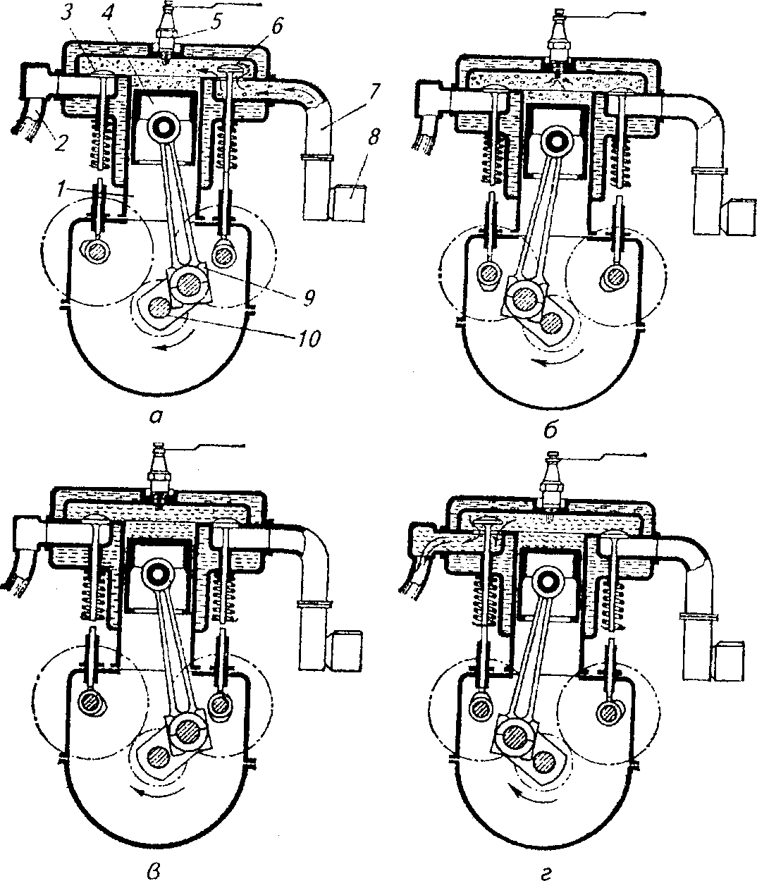
Fig. 1.6. Duty cycle of a single-cylinder four-stroke carburetor
engine:
A - intake stroke; b-contact compression; in-tact expansion; g-contact release; 1 - cylinder; 2 -
Exhaust pipe; 3 - Exhaust valve; 4- piston; 5 - sparkling incendiary candle; 6 -
Inlet valve; 7-intake pipe; 8- carburetor; 9-rod; 10- crankshaft
Compression Tact. With a further rotation of the crankshaft 10 (Fig. 1.6, b)the piston moves from NMT to v.m.t. At this time, the intake 6 and graduation 3 the valves are closed, so the piston compresses the working mixture in the cylinder. In the compression stroke, the components of the working mixture are well mixed and heated. At the end of the compression stroke between the electrodes of the spark plug 5, an electrical spark arises, from which the working mixture ignites. In the process of fuel combustion, a large amount of heat is released, the pressure and temperature of the gases increase.
Tact expansion. Both valves are closed. Under the pressure of expanding gases, the piston moves from the IDT. to n.m.t. (Fig. 1.6, at)and with the help of the connecting rod 9 rotates the crankshaft 10, doing useful work.
Tact release. When the piston approaches nmt, the exhaust valve opens. 3 and the exhaust gases under the action of excess pressure begin to exit the cylinder into the atmosphere through the exhaust pipe 2. Further, the piston moves from N. m. to v.m.t. (Fig. 1.6, d)and pushes the exhaust gases out of the cylinder.
Duty cycle of a four-stroke diesel engine.Unlike a carburetor engine, air and fuel are introduced separately into the cylinder of a diesel engine.
Intake stroke The piston moves from the rm. to n.m.t. (fig. 1.7, but),the inlet valve is open and air enters the cylinder.
Compression Tact. Both valves are closed. The piston moves from N. m.t. to v.m.t. (Fig. 1.7, b) and compresses the air. Due to the high degree of compression (on the order of 14 ... 18), the air temperature becomes higher than the auto-ignition temperature of the fuel.
At the end of the compression stroke, at a piston position close to i.d., liquid fuel starts to be injected into the cylinder through the nozzle. The nozzle device provides fine atomization of fuel in compressed air.
The fuel injected into the cylinder mixes with the heated air and the remaining gases to form a working mixture. Most of the fuel ignites and burns, the pressure and temperature of the gases rise.
Tact expansion. Both valves are closed. The piston moves from the rm. to n.m.t. (fig. 1.7, at).At the beginning of the expansion stroke, the rest of the fuel burns.
Tact release. The exhaust valve opens. The piston moves from N. m.t. to v.m.t. (fig. 1.7, d)and through the open valve pushes the exhaust gases into the atmosphere.
In the described engines, during the working cycle, only in the expansion stroke, the piston moves under the pressure of gases and, through the connecting rod, drives the crankshaft into rotational motion.

Fig. 1.7. Duty cycle of a single-cylinder four-stroke diesel engine:
but- intake stroke; b - compression stroke; at- expansion tact; g -release cycle
When performing the remaining cycles - release, intake and compression - you need to move the piston, rotating the crankshaft. These cycles are preparatory and are carried out due to the kinetic energy accumulated by the flywheel in the expansion stroke. A flywheel with significant mass is attached to the end of the crankshaft.
A diesel engine has the following main advantages as compared with a carburetor engine: an average of 20 ... 25% (by weight) less fuel is consumed per unit of work produced; work on cheaper fuel, which is less fire hazard. Disadvantages of a diesel engine: a higher pressure of gases in the cylinder requires increased strength of parts, and this leads to an increase in the size and weight of the diesel; its launch is difficult, especially in winter. Good economic performance of diesel engines led to their widespread use as engines for tractors, trucks and cars.
SUPPLY SYSTEM
The power, efficiency, reliability, reliability and durability of the engine in various operating conditions, the toxicity of exhaust gases significantly depend on the operation of the power supply system.
The power systems of carburetor engines and diesel engines differ significantly in their methods of mixing, ignition and combustion. So, in the carburetor engine fuel from the tank 2 (fig. 1.10, but)diaphragm pump sucked 4, coarse filter passes 3 and is pumped into the fine filter and then into the carburetor float chamber 8 . As the crankshaft rotates and the pistons move in the engine cylinders, a vacuum is created in the carburetor. As a result, fuel and air are sucked into the carburetor. The fuel is sprayed in the air stream and evaporates, forming a combustible mixture. Next, the combustible mixture through the inlet pipe 9 enters the cylinders and burns there. The exhaust gases are discharged into the exhaust pipe. 11 pass muffler 12 and are released into the environment.
In carburetor power systems, the fuel pump supplies 1.5 ... 2 times more fuel than is necessary for the engine to operate at full load. Excess fuel is returned through the jet 6 and a diverting fuel line to the tank, ensuring good removal of bubbles of steam and air.
In the diesel power supply system (Fig. 1.10, o), the supply and purification of air and the removal of exhaust gases do not essentially differ from similar processes in the power supply system of a carburetor engine. Fundamentally, the system differs in fuel supply and mixing devices, the main ones being the high-pressure fuel pump. 5 and nozzle 7 .
From the fuel tank 1 through the fuel line through the coarse filter 2 fuel is sucked up by a booster pump 3 and fed through a fine filter into the cavity of the high-pressure pump 5, with the help of which the fuel is metered, is fed through the high pressure fuel line and through the nozzle 7 injected into the cylinder. Excess fuel supplied from the cavity of the high-pressure pump through the pipeline 6 returned to the tank.
The simplest carburetor (Fig. 1.11) consists of a float chamber 2 with a float 1 , stop needle 4, jet 12 with sprayer 9, diffuser 8 throttle 10 and air 7 dampers and mixing chamber 11 . Fuel from the tank through the fuel line 3 enters the float chamber 2 and fills it. When the fuel level in the float chamber reaches the upper limit, the float 1 will press the locking needle 4 to her saddle and the flow of fuel will stop. When lowering the level of the float drops and the needle will open access to the fuel in the float chamber.

Fig. 1.10. Power systems:
but - carburetor engine: 1 - fuel gauge; 2-fuel tank; 3 - filter sump; 4 - diaphragm pump; 5-fine filter fuel; b - jet fuel flow; 7 air cleaner; 8- carburetor; 9-intake manifold; 10 - engine; 11 - exhaust pipe; 12 - muffler; b -diesel engine: 1 - fuel tank; 2 - coarse fuel filter; 3 - fuel pump; 4- fine fuel filter; 5-fuel high pressure pump; 6- fuel line of excess fuel; 7-nozzle; 8 - air cleaner; 9-tube for removal of leaked fuel; 10- fuel gauge
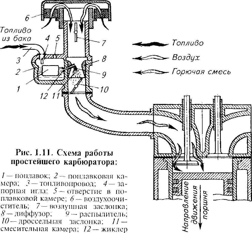
From the float chamber fuel through the jet 12 enters the sprayer 9, the outlet of which is located in the mouth of the diffuser 8. So that the fuel does not flow out of the atomizer when the engine is not running, the outlet of the atomizer is located 1 ... 2 mm above the fuel level in the float chamber.
During the intake stroke with open air 7 and throttle 10 the vacuum valves from the cylinder is transferred to the mixing chamber 11 and causes air movement in it in the direction indicated by the arrows. The vacuum in the mixing chamber can be adjusted throttle 10 and air 7 flaps.
The air sucked into the engine cylinder passes through the air cleaner in sequence. 6, pipe and diffuser 8. As the flow area in the throat of the diffuser decreases, the air velocity in it increases and the vacuum increases. Due to the difference between the atmospheric pressure in the float chamber and the vacuum in the diffuser, the fuel flows out of the atomizer. The jets of air move through the diffuser at a speed about 25 times greater than the speed of the fuel droplets coming from the sprayer. Therefore, the fuel is sprayed into smaller droplets and, mixing with air, forms a combustible mixture that enters the engine cylinder. As a result of atomization, the surface of contact between the fuel particles and the air increases, the fuel evaporates intensively.
The simplest carburetor cannot change the composition of the combustible mixture depending on the various engine operating conditions. Therefore, the following additional devices are included in the design of a modern carburetor: starting; idling (for engine idle and low loads); the main dosing (ensures consistency of the depleted, i.e., economical, composition of the mixture in a wide range of average loads); economizer (enriches the mixture in heavy load mode by supplying an additional amount of fuel to the mixing chamber); accelerator pump (enriches the mixture with a sharp opening of the throttle).
In the power supply system of engines operating on compressed and liquefied gases, as in a carburetor engine, the mixture of such a gas with air is prepared in a carburetor-mixer. Such engines provide short-term operation on gasoline.
The combustible mixture in diesel engines is formed inside the working cylinders. At the end of the compression stroke, fuel is injected into the diesel cylinders under high pressure through a nozzle, which is atomized and self-igniting due to the high temperature of the compressed air.
The main unit of the diesel power supply system is a fuel pump. 5 (see fig. 1.10, b).It serves to supply fuel under pressure to the injectors (at a certain moment) and dispense fuel in accordance with the mode of operation of the engine. Most automotive engines have sectional (in-line or V-shaped) fuel pumps. Each pump section operates as follows.
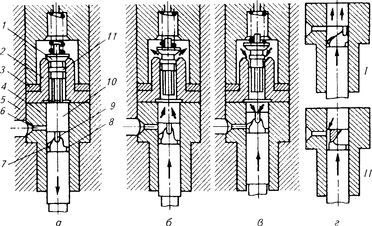
Fig.1.12. The scheme of the diesel fuel pump section:
but- filling the above-plunger space with fuel: b-pump plunger; at-fuel cutoff (cutoff); g- the extreme position of the plunger; / - maximum fuel supply; // - fuel supply is turned off; 1 - discharge (non-return) valve; 2 -valve seat; 3- copper sealing ring: 4 - plunger sleeve; 5-body pump (fuel) section; 6-side opening in the sleeve; 7 - single edge of plunger; 8- ring undercut; 9 - longitudinal groove; 10 -plunger; 11 -unloading belt
When moving down the plunger 10 (fig. 1.12) fuel from the opening of the hole 6 in the sleeve 4 enters the extraplunger space. When the plunger moves upward in the initial period, fuel is displaced from the sleeve through the hole 6. When the upper edge of the plunger 10 will block this window, in the above-plunger space of the liner the pressure starts to increase. Under the action of high pressure opens the discharge valve 1 and fuel is supplied to the injector through the fuel line.
With further movement of the plunger cut-off edge 7 opens hole 6 and the fuel flows from the above-plunger space (this is a high pressure space) through the longitudinal groove 9, annular recess 8 and side opening 6. The pressure in the aboveplunger space drops sharply, and the pressure valve in the fuel line under the effect of excessive pressure in the fuel line 1 pressed against the saddle 2. As a result of this, the plunger space and the fuel line are separated.
Cylindrical corbel discharge valve 1 called unloading. When the plunger moves, this belt acts like a piston, freeing some of the volume
high-pressure fuel line, which leads to a sharp decrease in pressure in the fuel line and a quick fit of the nozzle needle, and consequently, to a sharp cut-off of fuel injection.
The amount of fuel supplied depends on the active (working) stroke of the plunger. In Figure 1.12 (position I) shows the maximum fuel supply. When turning the plunger clockwise (as viewed from above), the feed decreases and counterclockwise increases. If the plunger is rotated so that the longitudinal groove 9 the plunger will be against the hole 6, then there will be no fuel supply (Fig. 1.12, position II).
REGULATORS OF FREQUENCY OF ROTATION OF THE MOTORED CRANKSHAFT
During the operation of tractors and automobiles, the engines operate with variable loads, which always leads to a violation of the correspondence between engine power and external resistances. This causes a change in the engine speed and the speed of the tractor or car. The operation of the engine with continuously changing speeds leads to disruption of technological processes in the production of agricultural work, where in most cases a constant speed of movement of the machine or unit and a constant PTO rotation speed are required.
In order to maintain a given high-speed mode of operation with a sharply varying external load, the engines of modern tractors and automobiles are equipped with regulators.
A regulator is a device that automatically maintains a given frequency of rotation of the motor shaft by affecting the engine control unit. In carburetor engines, the regulator acts on the throttle valve, changing the amount of combustible mixture entering the engine cylinders, and in diesel engines - on the rail of the fuel pump, changing the fuel supply sections of the high-pressure fuel pump.
The most common centrifugal, pneumatic and pneumatic centrifugal regulators. According to the number of adjustable modes, there are one, two and all regulators.
LUBRICATING SYSTEM
According to the method of supplying oil to the rubbing surfaces of parts, lubricating systems are distinguished by spraying, under pressure and combined.
Lubrication by spraying and by adding oil to gasoline is used in tractor starting engines. In a lubricating system under pressure, an oil supply is provided to all moving parts under pressure using a pump, only such a system is not used in automotive engines. The combined lubricating system is used in all autotractor engines. This system provides a supply of oil under pressure to the most loaded and demanding parts. The rubbing surfaces of less loaded parts or parts that are hampered by the supply of oil under pressure (piston, cylinder, gear teeth, etc.) are lubricated by spraying.
Combined lubrication system works as follows. From the oil pan through the sump mesh is sucked by an oil pump and sent to the filter . Purified oil is cooled in an oil cooler and enters the tube in main oil line. From this line, the oil passes through the holes in the block to the crankshaft and connecting rod bearings and into the channel to the camshaft journals. Further drilling in the distribution and crankshaft oil goes to all necks. The oil trapped in the cavities of the connecting rod necks lubricates the connecting rod bearings. The normal mode of operation of the lubrication system is supported by three automatically operating valves: safety valve, thermostat valve and drain valve.
SOURCES OF ELECTRIC ENERGY
Electric energy on modern tractors (automobiles) is used for starting engines (starter), sound and light alarm systems, lighting the path, powering instrumentation and other purposes. All devices and devices included in electrical equipment are divided into sources and consumers of energy. Current sources on a tractor (car) include a generator and a battery, and consumers - a starter, alarm devices, lighting and instrumentation.
Accumulator batteryit is designed to power electricity consumers when the engine is not running and at low crankshaft speed, and also to power the starter when the engine is started. When the engine is running, it consumes the excess energy of the generator and, while charging, accumulates it. Tractors use lead-acid batteries of the charter type.
Generatordesigned to convert mechanical energy into electrical energy, which is necessary to power consumers when engines are operated at medium and high speeds and a battery is charged. On tractors use generators of direct and alternating current. On all modern tractors, alternators are installed, which are simpler in design than DC generators, more reliable in operation and have smaller overall dimensions. The generator is driven by a belt worn on an engine shaft pulley and an alternator pulley.
STARTING SYSTEMS
To start up the internal combustion engine, the rotation of the crankshaft needs to be brought to a certain frequency, providing mixing, filling the cylinders with fresh charge, compressing and igniting the mixture. When the air temperature is above 0 ° C, this rotation speed for carburetor engines must be at least 40 ... 50 min -1, and for diesel engines - at least 150 ... 250 min -1.
Start a diesel auxiliary gasoline engineused on some tractor diesel engines.
To facilitate the start-up of a diesel engine, the cooling systems of the starting engine and the diesel engine are interconnected, which ensures that the diesel is heated.
Electric starter start- The most common method suitable for automotive, tractor and starting engines. The scheme of the electric starter starting system is shown in Figure 1.15.
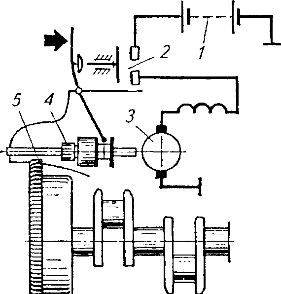
Fig. 1.15. The scheme of start-up electric starter:
1 - accumulator battery; 2 - switch: 3 -
Electric starter; 4- starter gear; 5 -
Gear Nenets flywheel engine
Electric starter 3 powered by a battery 1 low voltage current. During the start-up gear 4 starter engages with the ring gear 5 flywheel engine. The gear ratio between the starter gear and the flywheel ring is selected in such a way as to inform the engine crankshaft the speed necessary for starting. The starter is turned on for the period of start-up and switched off by a special mechanism immediately after the engine starts to work.
The system of starting diesel engines with the help of an engine is reliable in any temperature conditions, but its maintenance and operations at start-up are more difficult than in the case of starting with an electric starter.
The electric starter is designed for starting both carburetor engines and diesel engines. On the T-16M, T-25A, MTZ-80, K-701 tractors, the electric engines start the main diesel engines, and on the DT-85M, T-150, and T-150K tractors - starting engines.
The starter motor is a DC motor with a drive mechanism and a switch. Starters are produced with a mechanical and electromagnetic switching gear drive. The most common electromagnetic inclusion.
IGNITION SYSTEM
On modern cars use ignition systems of two types: classic and electronic (contact and contactless). The classical battery ignition system existed for a long time without fundamental changes and was improved only constructively. The limited capabilities of this system, the increased requirements for ignition systems and the development of electronics led to the creation of electronic ignition systems. The classic battery ignition system consists of low voltage power sources - a rechargeable battery. 21 (fig. 1.16) and generator, ignition coil 12, breaker 5 ignition switch 8, high voltage distributor 16, spark plugs 19 and connecting wires of low and high voltage.
When the ignition is turned on and the contacts of the breaker 5 are closed, the low voltage is supplied from the battery 21 or generator circuit: battery positive terminal - ammeter 22- ignition switch 8 - additional resistance (resistor) 9- primary winding 10 ignition coils 12- moving contact 2 breaker 5- “Weight” - negative battery terminal 21.
Passing through the primary winding 10, a low voltage current creates a smoothly increasing magnetic field around its turns.
When the rotating cam 4 move the lever 1 breaker 5, contacts 2 and 3 open, low voltage current in the primary winding 10 interrupted and the magnetic flux around it disappears. The vanishing magnetic flux will cross the turns of the primary 10 and secondary 11 ignition coil windings 12. As a result, in the primary winding an electromotive force (EMF) of self-induction of about 200 ... 300 V is induced, and in the secondary winding, having a much larger number of turns, - 18 ... 20 kV. The voltage in the secondary winding is enough to between the electrodes of the spark 19 create a reliable spark discharge igniting the working mixture.
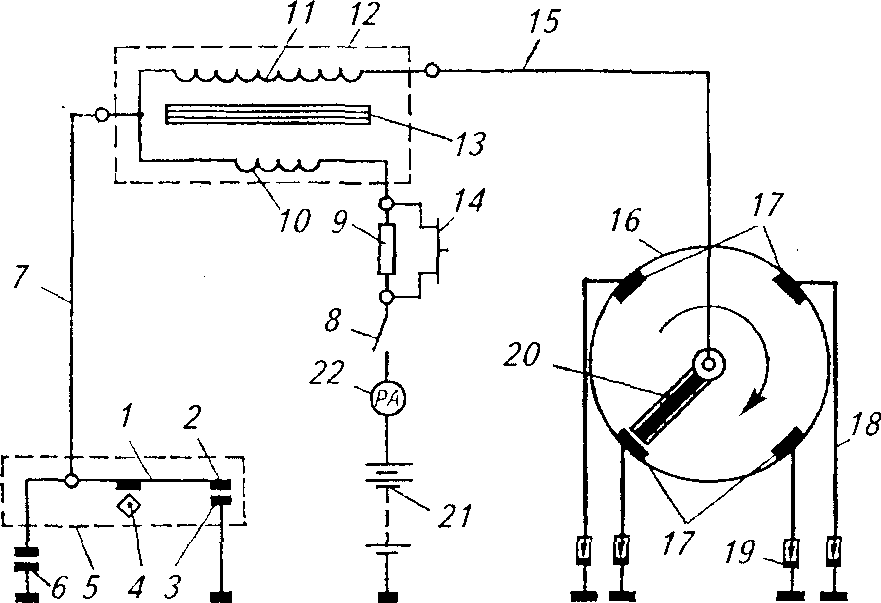
Fig. 1.16. Battery ignition circuit diagram:
1 - break lever; 2 - moving contact; 3 - fixed contact; 4 - cam; 5-breaker; 6 capacitor; 7, / 5 and 18- wires; 8 Ignition switch; 9 - additional resistance (resistor); 10 - primary winding; 11 - secondary winding; / 2-ignition coil; 13 - coil core; 14 - switch; 16 - distributor; / 7-electrodes; 19- spark plug; 20 - a rotor with a current-spreading plate (electrode); 21 - accumulator battery; 22 - ammeter
High Voltage Circuit: Secondary Winding 11 ignition coils 12 -the wire 15 high voltage - carbon rotor electrode 20- one of the electrodes 17 distributor caps 16- the wire 18- the central electrode of the candle - the side electrode of the candle - “mass” - negative output of the battery - ammeter 22- ignition switch 8- resistor 9- primary winding 10- secondary winding 11 ignition coils 12.
Then the breaker contact closes again, as the cam 4 comes off the lever protrusion 1 breaker.
EMF of self-induction slows down the process of current disappearance in the primary winding and leads to sparking between the contacts. 2 and 3 breaker, their oxidation and destruction. To reduce the effects of self-induced EMF in parallel with the breaker contacts, a capacitor is switched on 6, which in the period of contact opening is charged by self-induction current, and then, discharging in the opposite direction, accelerates the disappearance of the current in the low voltage circuit and, consequently, the magnetic flux, therefore the secondary voltage of the secondary circuit and contacts 2 and 3 the interrupter is protected from burning.
In starting engines apply the ignition system from magneto. The main device of such a system is a high-voltage magneto. It combines the functions of an alternator, a transformer, a chopper and a current distributor (there is no current distributor in the magneto single-cylinder engine).
LEAD BRIDGES
Drive axles are transmission mechanisms combined into one assembly unit, through which the engine torque is transmitted to the drive wheels of the tractor (car).
Depending on the destination, wheeled tractors can have one (rear) or two driving axles. In the latter case, these are off-road tractors (MTZ-82, LTZ-55A, K-701, T-150K).
In cars, the drive axle is usually one (less often two). The number of driving axles of trucks reaches three. In agriculture, all-terrain vehicles are widely used with two (UAZ-469, GAZ-66) and three (ZIL-131, etc.) driving axles.
Depending on the type and their purpose, in the rear axles of tractors and automobiles, in addition to the mechanisms that convert the torque transmitted to the propellers, they place auxiliary mechanisms - brakes, drives of the steering mechanism, PTO and other devices.
The main mechanisms of the driving axles of wheeled tractors are the main gear, differential, final gears and brakes (see. Fig. 1.17). In tracked tractors, instead of a differential, a steering mechanism is placed.
MAIN TRANSMISSION, DIFFERENTIAL, FINAL TRANSMISSIONS
main gearserves to increase the total gear ratio and transfer torque through the differential (or steering mechanism) and final gears to the driving wheels of the tractor (car).
The main transmission of the tractor is a single transmission consisting of a pair of bevel or cylindrical gears (see. Fig. 1.17). The main transmission of cars can be both single and double. Single gears are used on cars and trucks of small and medium capacity. Dual main gears consist of a pair of bevel gears and a pair of spur gears.
Differentialis a planetary mechanism designed to distribute torque between the leading axes of a tractor or a car and to ensure the rotation of the drive wheels with different frequency when moving along a curve or unevenness of the track. On a turn, uneven path, the driving wheels move along arcs of different lengths. If both wheels were located on a common shaft, their movement would be accompanied by skidding, tire wear and breakage. Therefore, the drive wheels are mounted on separate shafts - axles connected by a differential.
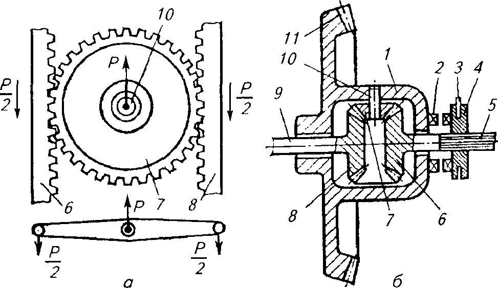
Fig.1.21. The scheme of the differential and its locking mechanism:
but - The scheme of the differential; b - differential circuit with locking mechanism; 1 - housing; 2- cam on the differential housing; 3- fork enable differential lock; 4 - movable cam clutch; 5, 9- semiaxes; 6, 8 - gears of semiaxes; 7 satellite; 10- satellite axis; 11 -formed bevel gear main gear
The principle of operation of the differential consider the scheme shown in Figure 1.21, but.Gear - satellite 7 (fig. 1.21, but)is engaged with the slats 6 and 8 (at real design is gears 6 and 8). To the axis 10 gears 7 force is applied R,tending to move this gear up.
If the resistance of the rails 6 and 8 displacement by force Rthe same forces act on their teeth Р / 2and the slats move upwards as a unit with gear 7. However, when resistance to movement of one of the slats, such as slats 6, will be bigger than reiki 8 , gear 7 begins to rotate around its axis and, rolling on the rail 6, move the rail 8 up faster. At the same time the speed of the rail 8 increases as much as the speed of the reiki decreases 6. If the resistance to movement of the rail 6 raise so that it stops, then gear 7, rolling on it, will carry along the rail 8 up, and the speed of movement of the rail will be 2 times the speed of movement of the axis 10.
Now consider the real scheme of the differential (Fig. 1.21, b).In the tides of the hull 1 on axis 10 loosely installed satellite gear 7 . The holes of the lateral tides of the hull serve as supports for semi-axes 5 and 9 stapered semi-axial gears mounted on them 6 and 8, in engagement with the satellite 7 . Rotation to the body 1 the differential is transmitted from the driven gear 11 main gear. If the semi-axes 9 and 5 the resistance to rotation is the same, then the satellite 7, wedged gears 6 and 8, fixed on axis 10 and the whole system rotates as a whole.
If the resistance to rotation of one axis, for example axis 9, will be greater than the resistance of the semi-axis 5, then satellite 7 turning on its axis will slow down the gear rotation 8 and speed up the gear rotation 6, just as it was in the example with the movement of gear 7 and the rails 6 and 8 (see fig. 1.21, but).
Changing the differential frequency of rotation of the axes with fluctuations of resistance on the wheels reduces the permeability of the tractor on moist or loose soil. In difficult soil conditions, it is better to turn off the differential to improve the grip of the wheels. For this purpose, tractors have differential locking mechanisms that are very diverse in design.
Differential locking mechanisms are divided into forced, automatic, and self-locking by the method of activation, and mechanical and hydraulic, according to the type of drive.
Forced (mechanical) differential lock occurs when the movable cam clutch engages 4 (see. Fig. 1.21, b), mounted on the slots of the tractor axle 5, with cams 2 on the case / differential. In this case, the rotational speed of the housing 1 differential and half-line 5 will be the same, that is, the differential will be locked.
The locking mechanism is turned on with a pedal (or knob), and it is turned off with a release spring when the force exerted by the driver stops.
Automatic differential lock allows the driver not to expend any effort - the process of switching the mechanism on and off automatically. Automatic differential locking is used on tractors MTZ-80, MTZ-82, T-150Kidr.
Final transfersrepresent one - or two-stage gear with a large gear ratio of gears. The final drive gears are located in the tractor rear axle housing (see fig. 1.17, o and at).
TRANSMISSIONS OF ALL-DRIVE MACHINES
To make full use of the coupling weight of a wheeled tractor (car) on some models, in addition to the rear axle, a front axle and a drive axle are installed. The use of such a bridge improves the performance and efficiency of the tractor (car) in conditions of poor adhesion of the wheels to the ground, helps to reduce fuel consumption, slipping and destruction of the soil structure.
To connect the gearbox to the front and rear axles, install a transfer case from which torque is transmitted through the drive shafts to the front and rear axles of the tractor or car. The transfer boxes are used on the MTZ-82, LTZ-55AM, K-701, T-150K tractors, as well as on GAZ-66, ZIL-131, UAZ-469 cars and others. The transfer case is attached to the gearbox body. Shaft with gears and gear couplings are placed inside the housing.
The transfer box is designed to distribute the engine torque between the driving axles of tractors and high-traffic vehicles. It can also function as an additional gearbox, increasing the overall transmission ratio.
Switching on and off of the transfer case with the forward running of the MTZ-82 tractor and increased slipping of the rear wheels occurs automatically due to the free wheel clutch. The transfer case device allows forcing the front drive axle to be forced both at the rear and at the front of the tractor, and also to disconnect the front axle, for example, during transport work when driving on a paved road, when using the front axle is impractical.
TRANSMISSION ELEMENTS, ALLOWING TO IMPROVE THE OPERATIONAL QUALITY OF TRACTORS AND CARS
In order to obtain the highest performance of MTA, multistage gearboxes with a wide range of speeds have been created. The number of gears (steps) of tractor gearboxes is 5 ... 32, and the range of main forward speeds is 0.5 ... 10 m / s and above. The greater the number of gears, the wider the opportunity to choose the speed corresponding to the optimal engine load, and therefore high performance and economical fuel consumption.
In some domestic (T-150, T-150K, K-701, MTZ-100, LTZ-155, etc.) and foreign tractors use transmissions with switching without breaking the flow of power. Gear shifting with gears of constant gearing while the tractor is moving is carried out by friction clutches controlled from the hydraulic system. This improves the performance of the unit from 6 to 20%, reduces fuel consumption and facilitates the driver’s work.

Fig. 1.23. Diagram of hydromechanical transmission:
but- torque converter: H- pumping wheel; T- turbine wheel; R -reactor, 1 - overrunning clutch; 2 -the primary shaft gearbox; 3- engine crankshaft; b - kinematic scheme of a stepped mechanical box 1 , 2, 3, 4, 5 - movable gears; 6, 7 - fixed gears
Due to the fact that the stepped gears do not allow the engine to fully load the engine in any load mode of operation and thus ensure optimal conditions for its operation, in the domestic and foreign engineering began to use continuously variable transmissions.
Consider the continuously variable transmissions widely used in the tractor industry.
Hydromechanical transmission consists of hydraulic and mechanical transmissions (Fig. 1.23). The steplessness of the transformation (transformation) of the torque in it is provided by the hydrotransformer, and a further increase in the moment - by a stepped transmission.
Torque converter includes: pumping wheel H,driven from the crankshaft 3 engine; turbine wheel T,rigidly connected to the primary shaft 2 gear boxes; reactor wheel R,coupled 1 free running with torque converter housing sleeve. All three wheels with profiled blades are placed in a common casing and form a closed annular volume filled with liquid (spun oil) and called a circulation circle.
The pumping wheel converts the mechanical energy of the engine supplied to it into the hydraulic energy of the working fluid flow. The working fluid thrown by the blades of the pumping wheel acts on the blades of a nearby turbine wheel and causes it to rotate. Flows of working fluid coming from the blades of the turbine wheel pass through the blades of the reactor wheel. The latter unfold the jet of working fluid in such a way as to provide them with the optimum direction when entering the pump wheel. Then the cycle repeats.
Continuously variable gears allow you to more flexibly maneuver the speed of movement, completely eliminates the loss of time to shift gears, improve the acceleration qualities of the unit, etc. All this allows you to increase productivity and reduce MTA fuel consumption.
Consequently, it can be concluded that not only transmissions with gear changes on the move, but also progressive continuously variable transmissions are promising for use on tractors.
AGRO-ECOLOGICAL ASPECTS OF THE INTERACTION OF THE RUNNING PART OF TRACTORS AND CARS WITH THE SOIL
The problem of abrasion and compaction of fertile soils has arisen as a result of an increase in the number of machines used in agriculture. In addition, their weight has increased significantly. Thus, the widespread K-701 tractor has a mass of more than 12 tons, and the KamAZ automobile has more than 7 tons.
As a result of this trend, the total area of wheel tracks (caterpillars) reaches 50 ... 200% of the area under cultivation, the density of the soil in the wake increases 1.1 ... 1.2 times as compared to the unconsolidated areas, its structure worsens. As a result, the yield decreases on the area of wheel and caterpillar tracks, and the resistance of the soil to the treatment of the machine's working elements increases.
It has been established that after the passage of tractors the soil structure changes: the number of lumps larger than 10 mm increases (by 15 ... 20%) and their number decreases accordingly to 0.25 ... 10 mm, the number of particles less than 0.25 mm sharply increases. Such a change in structure occurs to a depth of 30 ... 60 cm (depending on the mass of the aggregate, the multiplicity of passes along one track, the types and condition of the soil).
Wheels and caterpillars of machines compact the soil to a depth of 50 cm. The upper layers of the soil (up to 20 cm) are most strongly compacted. After the passage of machines, the density of the soil in the upper layers increases by 6 ... 20%. It is established that the increased density is maintained for 1 ... 3 years in the layers of soil that are not subjected to treatment, and increases with subsequent passes.
The change in soil density leads to a significant increase in its hardness. Thus, the hardness of sod-podzolic soils and chernozem in a layer of 0 ... 10 cm after a single pass of a tractor of types MTZ, T-150 and K-701 increases on average by 1.8 ... 5 times. With an increase in the multiplicity of passes, the hardness of the soil increases accordingly.
Soil compaction by road systems of machines occurs due to a decrease in its porosity, which leads to a decrease in the filtering capacity of the soil, and consequently, to a significant decrease in the access of moisture and air to it.
Wheeled and tracked tractors in a patch of contact with the soil create pressure for fractions of a second from 0.05 to 0.5 MPa. This pressure acts in the soil layer 0 ... 50 cm, decreasing with increasing depth. At such pressures and times of their application, humus-forming and soil loosening living organisms that live in its upper layers die. From contact with propellers, the structure of the top layer of soil is destroyed - it is crushed. As a result, the processes of soil erosion are intensifying - the most fertile components are eroded from it more intensively and are washed out. All this leads to a decrease in soil fertility, and consequently, crop yields.
To reduce the harmful effects of propulsion on the soil, it is advisable to use tracked tractors. However, they are less versatile than wheel.
To reduce the negative impact of the running systems of machines, reduce their pressure on the soil, use wide-grip working tools (this allows reducing the number of passes across the field and the area of tracks of wheels and caterpillars) and combined MTA (in this case, you can not only reduce the number of passes across the field, but also use the drive of working tools and trailers to increase traction without increasing the weight of the tractor), install low-pressure tires (0.08 ... 0.12 MPa) or arched tires, double the wheels, use a two-track constant th tramline for crops.
INFLUENCE OF CONTROL MECHANISMS AND BRAKING SYSTEM ON EFFICIENCY AND SAFETY OF WORK
The easier and more convenient the steering, the smaller the turning radius, the greater the speed when turning and the less energy spent on driving when moving along a given path, the better the steering and the steering, and therefore the higher its performance and efficiency.
Increasing the MTA working speeds leads to a deterioration of steering and quality of work when performing agricultural processes, and as the turning radii increase on the headlands, the soil becomes more compacted and, consequently, the yield of agricultural crops decreases.
So, the steering should ensure the preservation of a given direction of travel (a given course), and with appropriate impact, change it along the desired trajectory, on which driving safety depends.
The ability to forcibly reduce speed and stop quickly is the most important feature of the machine, which affects its performance (productivity, fuel consumption, etc.) and is of great importance for traffic safety.
The technical condition of the brake system significantly affect traffic safety. The braking efficiency at a speed of 40 km / h should correspond to the data in Table 1.5.
Tab. 1.5. Braking distance and permissible vehicle deceleration (initial braking speed 40 km / h)
Auto Braking distance, m, not more than Settled deceleration m / s 2
Passenger 16,2 5,2
Cargo 23 4
Road train 25 4
Table 1.5 shows the values of the stopping distance of cars from the beginning of the brake mechanism. However, the overall stopping distance of the car is actually greater. The components of the total stopping distance: the distance traveled by the car for the period from the moment the driver makes a decision to brake until the brake pedal is pressed (driver response time); the path traveled by the car during the actuation of the brake system; directly stopping distance when braking begins. Consequently, in reality, from a driver deciding to brake to a full stop, the car travels a much longer way. The reaction time of the driver is 0.4 ... 2 s, depending on his physical and psycho-emotional state. The response time of the brake system when it is fully operational should be 0.6 ... 0.9 s.
The stopping distance depends on the strength of the tire (tractor) tire adhesion with the road surface, the condition of the road surface, the speed of movement, the serviceability of the brake system, the condition of the tires and the air pressure in them. Compared with dry asphalt concrete, the braking distance is increased by about 30%, with ice - by 5 ... 10 times. All this worsens the safety conditions of work on tractors and automobiles. Braking distance is proportional to the square of the speed of movement. For example, if the speed of a car increases 3 times (from 20 to 60 km / h), then the stopping distance increases 9 times, etc.
STABILITY OF TRACTORS AND CARS. METHODS OF INCREASING LONGITUDINAL AND TRANSVERSE STABILITY
One of the important performance indicators of the tractor’s permeability is stability, which characterizes its ability to work on longitudinal and transverse slopes without overturning. There are longitudinal and transverse stability of the tractor. Stability is assessed by the static angles of the longitudinal and transverse slopes, on which the braked tractor without a trailer and a mounted machine can stand, without overturning. Assessing the stability of the tractor in the unit with the machine in the dynamics presents great difficulties due to the large number of interacting factors affecting the stability of the movement of the tractor-machine system.
Longitudinal stability.Tipping occurs when lifting, when the front wheels of the tractor and the car are fully unloaded. The entire weight of the car is perceived by the rear wheels. In this case, the rollover is determined by the coordinates of the center of gravity of the machine.
When driving downhill, tipping occurs with the rear wheels completely unloaded. In this case, the rollover is determined by the coordinates of the center of gravity and the distance between the axles of the wheels.
Transverse stability.When the tractor or car is parked on a cross slope, one of the sides is unloaded. When one of the sides is completely unloaded, a rollover occurs, which is determined by the track width and the vertical coordinate of the center of gravity. In this regard, when working on the slopes of wheeled tractors increase the track.
Large areas of fertile land in our country are located in mountainous areas, which necessitated the creation of special tractors of increased stability for mountain farming, which are also called steep slopes.
Ways to improve sustainability.In the simplest way to increase the longitudinal stability in the front of the tractor on the frame 2 (fig. 1.31, but)place special ballast weights 1 . This method is used to increase the longitudinal stability of the wheeled tractor when aggregating with heavy, rear-mounted machines, because when unloading the front wheels, the tractor’s handling is broken, and the weights contribute to restoring it.
One of the effective ways to increase the stability of the tractor in both the longitudinal and transverse directions is to lower its center of gravity as a result of reduced ground clearance. This method is applied on a modified model of the tractor LTZ-55AMN.
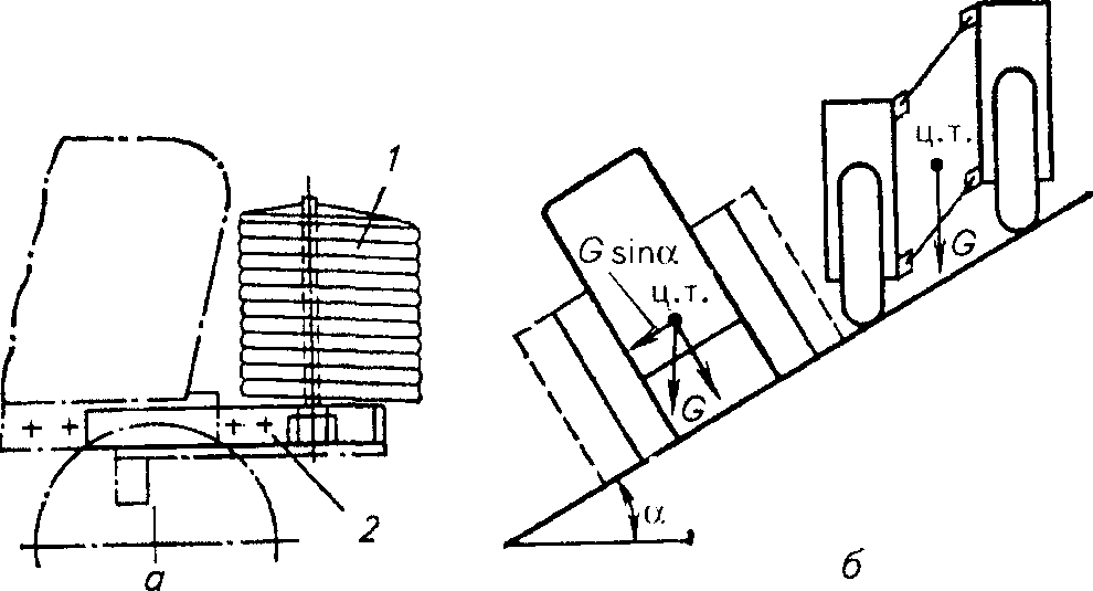
Fig. 1.31. Increased tractor stability:
but- ballasting with cargo: 1
- loads; 2- tractor frame; bhinge mechanism for stabilizing the skeleton
The tractor LTZ-55AMN is designed for general use and transportation of goods on slopes with a steepness up to 16 ° and flat terrain. It can also work on slopes with a steepness of up to 20 °, in areas with even microrelief and with limited speed. The height of the tractor is reduced in comparison with the base model by 0.34 m, and the agrotechnical clearance - by 0.32 m.
For safety reasons, a rigid frame was used in the cab to protect the operator in case of overturning of the tractor. An inclinometer alarm panel is installed in the cab under the instrument panel, warning the tractor driver of the tractor's roll limit.
The tractor, which is stationary on a slope, overturns under the action of force  . Where
  - its weight (Fig. 1.31, b).Tipping of the tractor will occur at a certain angle
 when the direction of the force will pass to the left of the pivot point. The danger of overturning will be reduced if the right and left parts of the tractor are connected by a hinge mechanism, which allows the tractor to maintain a vertical position in a certain range of slope values
  . This principle is implemented in the construction of some wheeled steep tractors.
The steady movement of such a tractor on a slope is provided by a leveling mechanism, made in the form of rotary final gears and free suspension of the front axle on the hinged parallelogram mechanism.
Tracked tractors are more suitable for working on mountain slopes, since their center of gravity is relatively low, dynamic stability is better and they are less susceptible to slipping from a slope. These tractors are used for the most energy-intensive work on the mountain, ravine and girder slopes with a steepness of up to 20 °, located at an altitude of up to 2 km above sea level.
For better safety, the crawler tractors are equipped with a special support, which with the help of a lever system and a hydraulic cylinder is installed in the direction of the roll and prevents tipping. The track and longitudinal base of these tractors are increased.
HYDRAULIC HINGED SYSTEM
The hydraulic hinged system includes an oil pump, a distributor, hydraulic cylinders, an oil tank, shut-off and rupture devices and oil lines, a hitch mechanism, and in the tractors MTZ-80 and MTZ-82- an additional hydraulic weight enhancer (GSV) and a regulator of soil tillage .
Figure 1.32 shows a diagram of the action of the hydraulic hinged system (FGP and tillage depth control conditionally are not connected to the hydraulic system). Oil pump 1 (fig. 1.32, but)from the tank 2 pumps oil into the distributor 3. Spool 4 distributor with crank 5 can be installed in four positions: lift (P), neutral (H). lowering (O) and floating (Pl). When the spool is in position P (shown in Fig. 1.32, b)oil from the distributor is injected through the oil pipe into the cavity Bhydraulic cylinders 6 and mixes the piston in it towards the cavity BUT.In this case, the piston rod through the hitch mechanism 8 raises the gun 9. At the same time, from the cavity BUToil is displaced by the piston and discharged through the distributor to the tank. Conventionally, the path of the oil in the distributor is shown in Figure 1.32, 6.
When the handle is set to the H position, the spool locks the holes leading to the oil pipes of the main hydraulic cylinder, so the piston in it is stationary and the tool remains in the set position, and the oil pump, idling, pumps oil through the distributor to the tank. When the handle is set to the forced lowering position, the pump delivers oil to the cavity BUTthe hydraulic cylinder, the instrument is lowered by the piston, and oil is forced out of the cavity by it Bin the tank. If the handle is set to the floating position, the spool will be located so that the oil will flow through the distributor from one cylinder cavity to another. This will allow the tool to rise and fall, copying the soil surface with a support wheel. The pump will run idle, as in a neutral position.
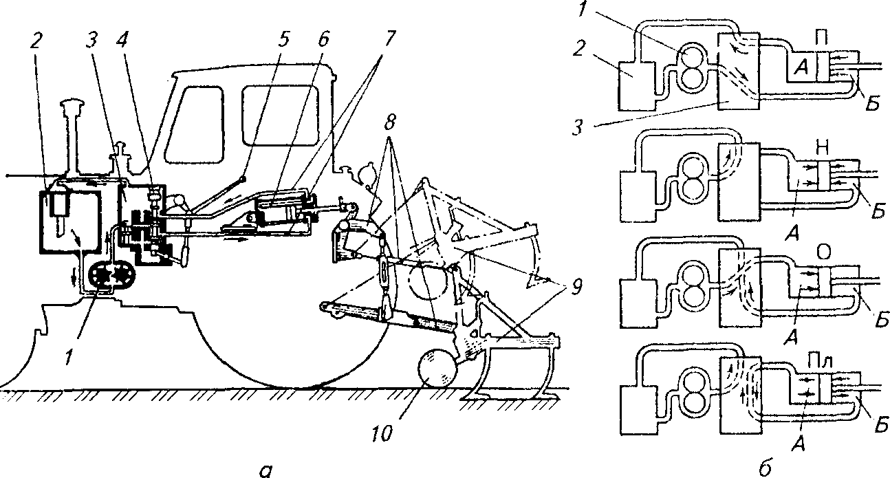
Fig. 1.32. Scheme of the hydraulic mounted system of the MTZ-80 and MTZ-82 (I) tractors and the oil path in the hydraulic system(b):
1 - pump; 2- oil tank; 3 - distributor; 4 - valve spool; 5- spool handle; 6 - hydraulic cylinder (main); 7-oil pipelines; 8 - hitch mechanism; 9- mounted implement; 10- gun support wheel
When a wheeled tractor operates with heavy agricultural machinery, as well as on wet soil, its driving wheels are significantly stalled, and the speed and productivity of the unit are reduced. In order to reduce the slipping of the driving wheels of the tractors, they can be added with the help of grip weight increasers due to the part of the mounted agricultural implement or machine attached to the tractor.
Gauges of coupling weight is divided into mechanical (in tractors T-25A, LTZ-55) and hydraulic (in tractors MTZ-80, MTZ-82). Mechanical loaders change the load on the drive wheels due to the rearrangement of the center linkage of the hitch system. The greater the angle of inclination of the central thrust, the more the drive wheels are loaded.
The hydraulic device of the coupling weight of the MTZ tractors is installed between the distributor and the main hydraulic cylinder of the separate aggregate system. The principle of operation of FGPs is based on the creation of a back-up force in the hydraulic cylinder, aimed at raising the implement. When setting the FGP for work in field conditions, it is necessary to create such a force of the overpressure that the pressure of the working bodies to the bottom of the furrow during movement was minimal, i.e., that the track of the support wheel of the machine was shallow.
The tillage depth regulator controls the action of the hydraulic cylinder through the distributor, restores the depth of tillage when it deviates from the originally specified. There are high-altitude, power, positional and combined methods of regulating the depth of tillage. All of these methods are carried out by special regulators included in the hydraulic mounted system.
The oil pump serves to supply oil from the tank to the working cavities of the hydraulic cylinders. In hydraulic systems of tractors, gear pumps NSh-32K, NSh-46U, Sh-50K, NSh-67K and others are installed. The hydraulic system pump, unlike the pump installed in the engine lubrication system, supplies high-pressure oil (12.5 ... 16.0 MPa).
The distributor is designed to distribute the oil pumped by the pump between the hydraulic cylinders and the hydraulic booster, maintain the set pressure, automatically switch the hydraulic system to idle - bypassing the oil into the tank and protecting the hydraulic system from overloads. On tractors, valve-spool-type R-75-VZA distributors are installed in three sections, four-position with automatic transfer of the slide from the working position to the neutral position.
The hydraulic cylinder serves for raising and lowering agricultural implements hung on the tractor. The tractor is equipped with one main cylinder complete with a hinge mechanism and two remote ones, which are usually placed on agricultural machines. The cylinder consists of a housing, covers, a piston with a rod, channels with a limiting valve, and coupling bolts. The industry produces six types of hydraulic cylinders: Ts-55, Ts-90, 1.1-100. C-110. P-120, C-125 (here C is the cylinder, the number is the internal diameter of the cylinder, mm).
Hydraulic system tanks are cast (in MTZ tractors) and stamped (in DT-75M, T-150K, K-701 tractors, etc.). The volume of tanks is chosen on the basis of half the theoretical performance of the pump, which ensures the operation of the system without overheating and foaming the oil. All tanks are equipped with filters installed on the end of the drain pipe, and safety valves.
Hydraulic pipelines are subdivided into seamless steel tubes of high pressure and rubber-metal hoses. They are interconnected by means of locking (connecting) and discontinuous couplings. Locking couplings allow you to disconnect the hoses without draining the oil from the system, due to the presence of spring-loaded ball valves. The number of locking sleeves corresponds to the number of hoses connected to the cylinder. Explosive couplings automatically open at an axial force of 200 ... 250 N (in case of emergency disconnection of the implement) without breaking the hoses and losing oil from the system, since the ball valves installed in them securely close the pipelines.
The tractor consists of the following mechanisms and systems:
- The skeleton;
- Engine and its systems;
- Transmissions;
- Chassis;
- Aggregation systems;
- Lent and control systems;
- External and internal equipment.
- The skeleton and the layout of the tractor
Are known the three most common types of wreck tractors:
- frame;
- semi-frame;
- frameless
Wheeled tractor layout
Universal wheeled tractors are built according to two classic schemes: with enlarged rear wheels and with wheels of the same diameter.Tractors with extended rear wheels
Tractors with enlarged rear wheels, for example, MTZ -80 have a semi-frame frame. At the same time, part of the body, perceiving forces arising from the action of weight, tractive effort and inertial forces of the tractor, perceive the crankcase of the traction nodes and the double-girder half-frame in front of the tractor. The front axle, the front engine mount and its systems, and the front attachment are attached to the semi-frame.These tractors have a front engine layout and a rear wheelhouse. The semi-frame frame simplifies the design of the tractor, but makes it difficult to disassemble and assemble it during repair. In addition, large variable loads on the crankcases of transmission units reduce its durability and do not allow the use of high-precision gearing. Steering is done by the front wheels.
Tractors with wheels of equal diameter
Tractors with wheels of the same diameter, for example, K-700, as a rule, have a frame frame consisting of two half-frames connected by hinges. On each of the half-frames installed on the drive axle. The rotation control is carried out by turning the half-frames.Such an arrangement allows the use of wheels of increased diameter and width, but impairs tractor stability, since the center of gravity shifts away from the longitudinal axis when turning. The arrangement of tractor units on semi-frames may be different. For example, the K-700 tractor has an engine, gearbox and cab located on the front half of the frame, while on the rear half there is only a linkage mechanism.
At tractor-tractor MOAZ -531, the engine and power take-off reducer are located on the rear half-frame, and the cab and gearbox are on the front.
Wheel self-propelled chassis
The layout of the tractor wheel universal self-propelled chassis is built on the basis of the need to place heavy or large-sized machines, tools or a tipper body on the tractor frame. Therefore, self-propelled wheeled chassis usually have a compact power unit (engine complete with transmission), located at the rear. The front part is an open frame.Tracked tractor layout
Classical for tracked tractors is a scheme with a front engine and rear control station. Such a scheme is optimal for an agricultural tractor, since it provides, firstly, a good overview of mounted machines and tools, and on the other hand, the front center of gravity. The forward location of the center of gravity is necessary for the agricultural tractor because its rear end is loaded with weight and the response of the attachment in the process.There are other schemes, for example, with the front cabin and rear engine. This scheme is applied on an industrial tractor T-330. The front cabin position provides a good overview of the dozer equipment, and the rear engine position provides optimum weight distribution (due to the fact that the front end is loaded with weight and reaction of the dozer blade). Tracked tractors can have a frame, semi-frame or frameless frame. The type of the crawler tractor frame is determined by its suspension.
Frame frame have tractors with individual or pair of elastic suspension support rollers, for example tractors DT-75 and T-180. In this case, the tractor units are mounted on a common frame, which is a welded metal structure. Usually, the frame of the tractor consists of two longitudinal beams-spars connected by several transverse jumpers. Such a scheme makes it easy to disassemble and assemble the tractor during repair.
Another advantage of the frame frame is the possibility of using lightweight body assemblies and assemblies, which are unloaded from the weight of the tractor and its tractive effort. However, the welded frame has low rigidity, which causes relative displacement of the shafts of the tractor units and requires their connection by elastic couplings or cardan joints. These elements have a limited resource and can not transmit high torque.
The semi-frame frame is equipped with semi-rigid tractors, such as the T-4 and T-130.
Frameless frame have tractors with a group of elastic or rigid suspension of road wheels to the balance beam, such as tractors T-330. The advantage of the frameless frame - high rigidity, which allows to refuse from the elastic couplings between the shafts of the units. The lack of a frameless frame - the difficulty of mounting on it mounted systems and equipment of the tractor. Tractor units with a semi-frame and frameless frame have hatches in the walls of the crankcase, allowing inspection and repair of individual mechanisms and systems without disassembling the entire tractor.
Engine
The main type of engine of modern tractors is a four-stroke diesel, as it has high values of torque at low speeds and high efficiency. Gasoline engines find use on ultralight lawn and garden and lawn tractors, and gas turbines on heavy-duty ones.There are also tractors with an electric motor (for work in enclosed spaces), which receive electricity via cable or trolley wires.
Previously produced tractors with steam engines, with petrol or kerosene carburetor engines, with kerosene calorific engines.
Diesel Tractors
On light tractors of up to 1 ton-force tractors, diesel-powered air-cooled diesel engines, which do not have pressurization power up to 50 hp, are widely used. Such engines are simple in design, cheap enough, not demanding on the quality of fuels and lubricants, compact. Their disadvantages are the complexity of regulating the thermal regime, increased noise and large energy losses for the fan drive. Among domestic tractors, air-cooled engines are equipped, for example, with T-16 self-propelled chassis and T-25 and T-40 row-crop tractors.On heavier tractors, diesel engines are used for liquid cooling. However, an air-cooled 330 hp engine was developed for the T-330 industrial tractor.
The main part of the skeleton of a tractor engine - block-housing is usually a cast-iron or aluminum casting of complex shape. The crankcase incorporates cylinder liners, crankshaft bearings and bearings for the timing parts. Bottom halves of the crankshaft supports are fixed to the crankcase block. The lower part of the crankcase closes the oil pan, which can be lightweight mounted or carrying. In front of the crankcase block is located the gas distribution mechanism and auxiliary systems. The back of the crankcase is connected to the crankcase of the transmission units.
Air-cooled engines typically do not have a single crankcase. Their cylinders are separate, removable with radiator fins on the outside for improved heat dissipation.
The cylinder head of a tractor engine is usually an aluminum alloy casting, but it can also be cast iron. In the cylinder head are valves and other parts of the gas distribution mechanism, gas exchange channels, seats for fuel injectors. In addition, a combustion chamber of unseparated or divided types can be placed in the cylinder head. The cylinder heads of air-cooled engines are individual, have an external radiator. Cylinder heads of liquid cooling engines are usually common to several cylinders and have channels inside for circulation of coolant.
The crank mechanism of the tractor engine has no significant differences from the similar node of the automobile engine. However, due to the fact that tractor engines are forced not by the frequency of rotation, but by the average pressure of the cycle, the piston of the tractor engine perceives large forces from the pressure of gases and smaller inertial forces as compared to the automobile ones. Therefore, the pistons of tractor engines are usually cast iron, although aluminum pistons are widely introduced on modern models of tractors. Pistons of powerful tractor engines, as a rule, forcibly cooled with oil.
Crankshafts of tractor engines are usually full-support, that is, they have a support on each main journal. The bearings are lubricated under pressure bearings. On tractors, forged steel crankshafts are most prevalent, but previously there were also prefabricated ones.
Tractor engines usually have an in-line or V-shaped arrangement of cylinders. The row arrangement is typical for row-crop tractors, since they need to have as small a width as possible to work in between rows. On other types of tractors, V-engines have found wide application, since they are smaller than in-line engines and have a shorter and therefore more rigid crankshaft.
Tractors engines typically have fewer cylinders compared to automotive engines of the same working volume and a smaller ratio of cylinder diameter to piston stroke (that is, tractor engines are more long-stroke). This is due to lower speed and the need to obtain more torque. However, recently there has been a tendency to an increase in the rotational speed of tractor engines and their basic ratios approach the values characteristic of automobile engines.
The gas distribution mechanism of tractor engines has few differences from the similar mechanism of automobile engines. For tractor engines, it is typical to use a mechanism with valves in the cylinder head and the camshaft in a crankcase with motion transmission by means of rods and rocker arms. This scheme simplifies the drive of the camshaft, and its main drawback is the high inertia that is not essential for the tractor engine due to the low speed.
Tractors of old types, for example DT-75 as part of the timing mechanism, have a decompression mechanism that allows the initial promotion of the engine crankshaft when started without compression in air cylinders. The decompression mechanism was usually a camshaft acting on the inlet rocker arms, keeping the latter in the open state during decompression. On modern tractor engines, in connection with the improvement of starting systems, there are no decompression mechanisms.
The lubrication system of tractor engines is usually combined. The crankshaft and camshaft bearings are lubricated under pressure, and the remaining friction pairs - by spraying. As a rule, the lubrication system has one pump and an oil bath in the crankcase. However, powerful tractors have dry-sump engines, where the oil from the crankcase is collected by a special pump into an oil tank, in which it is settled and freed from foam.
The dry sump system is more complex, but provides a significantly longer oil life, since the latter is exposed to the negative effects of heat and crankcase gases for a significantly shorter time.
On old types of tractors, the oil was cleaned by centrifugal centrifuges with hydrodynamic rotor drive. Modern tractor engines use paper filters of automobile types as well as combined cleaning systems.
Thermal loads on oil in tractor engines are significantly higher than in automobile engines, therefore the oil must be cooled. For this purpose, oil radiators or ribbed and air-blown surfaces of oil pans or tanks are used in the lubrication system. On new types of tractors, in connection with the use of high-quality oils that can operate at elevated temperatures, oil radiators may be missing.
The power supply system of tractor engines with air must ensure high efficiency of its cleaning, since tractors usually work in conditions of high dustiness of air and air pollution with trash, foliage, and insects. Tractor engine air cleaners perform multi-stage. The first stage ensures the removal of the largest particles: a heap, foliage, insects. Usually it is performed in the form of a cylinder of metal mesh, rotating with great frequency. Centrifugal forces arising during rotation do not allow large particles to settle on the grid. The second stage removes a significant amount of dust.
To do this, use cyclone cleaners. A significant amount of dust collected by cyclone catchers requires automation of their cleaning process, preferably without stopping the tractor engine. This is usually done by an ejection system that works with exhaust energy — dust from the cleaner pan is sucked into the exhaust system and removed through the exhaust pipe. The third stage provides final air purification. On old types of tractors, oil-filled fiber filters were used for this purpose, and on modern types, dry paper (like automobile) filters were used. When tractors operate in coal cuts in the intake tract, a humidifier filter is installed, effectively precipitating particles of coal dust.
Tractor engines usually supply turbocharging, which allows to significantly increase engine power at low speeds. In addition, the use of an adjustable turbocharger allows for a constant engine power in a wide range of rotational speeds. Such engines are called constant power engines (DPM). The use of engines of constant power allows you to significantly simplify the transmission of the tractor, reducing the number of gears and facilitate the work of the driver. Currently, constant power engines are becoming widespread on tractors of all classes.
The fuel system of tractor engines has no significant features. It consists of fuel filters, booster pump, high pressure fuel pump (fuel pump), injectors and a regulator. Older types of tractors had a block injection pump and a mechanical centrifugal regulator. Such systems are simple in design, but have several disadvantages: low stability of rotational speed, increased fuel consumption and smoke during transient conditions.
Tightening requirements for efficiency and environmental compatibility of tractors leads to the use of more complex fuel systems with electronic control of the amount of fuel injected and injection timing. The electronic control system of the modern tractor dispenses the fuel supply taking into account the actual filling of the cylinders with air, the magnitude and tendency of the engine load change, the speed and pulling force of the tractor, as well as a number of other factors. These measures have allowed to reduce fuel consumption from 180 g / hp * h, typical for tractors of the 60s - 70s to 100 g / hp * h, excluding the emission into the atmosphere of toxic products of incomplete combustion of fuel.
Starting tractor diesel enginescan be done in various ways:
- electric starter;
- starting petrol engine (tractors operating in cold climates);
- compressed air (DET-250);
- inertia starter with manual drive.
Gas Turbine Tractors
Power of diesel engines of agricultural tractors as a rule does not exceed 500 hp Its further increase is associated with an unjustified increase in the weight of the tractor, which will lead to an increase in the specific pressure on the soil and will not allow to realize the main advantage of an energy-saturated tractor - high speed of work. Only on industrial tractors, which require a large mass, diesel engines with a capacity of about 1000 hp are needed to create large tractive effort.At the same time, the technologies of cultivation of the soil improved in recent years allow the efficient use of more powerful agricultural tractors. An important reserve for increasing the energy content of tractors is the use of gas turbines having a low specific gravity. For example, in the United States for a number of years, Big Roy and Elis Walters have been manufacturing gas turbine tractors with power up to 700 hp.
Attempts were made to produce gas turbine tractors in the USSR. Thus, the Kirov Plant together with NATI developed the Kirovets-Turbo gas turbine tractor based on the T-80 gas turbine power plant. The wide application of gas turbines on tractors is hindered by the high frequency of rotation of the output shaft of the turbine (about 20,000 rpm), which complicates the transmission of the tractor and the increased fuel consumption compared to diesel engines.
Gasoline Tractors
At present, only extra-light tractors are equipped with gasoline engines (micro-tractors, motoblocks, lawn tractors, riders). The advantages of gasoline engines are easy start, low cost and relatively simple maintenance. Disadvantages - high specific fuel consumption and low torque, which complicates the transmission of the tractor.Transmission
The transmission of the tractor is usually multi-threaded, that is, it transmits engine power not only to the running gear, but also to drive aggregated machines and auxiliary mechanisms.Modern tractors are equipped with transmissions of several different types:
- Mechanical step;
- Mechanical stepless;
- Hydromechanical;
- Hydrostatic;
- Electrical and electromechanical.
Mechanical manual transmissions
Mechanical stepped transmissions have the lowest cost and are most compact with the same amount of transmitted power, but do not allow you to smoothly adjust the speed and tractive force of the tractor.The mechanical transmission of the tractor consists of:
- main friction clutch;
- gear boxes;
- central (main) transmission;
- final gears;
- transmission power take-off.
The main friction clutch allows you to separate and smoothly connect the engine and transmission of the tractor. The greatest use on tractors was found in dry-type clutches, since they are characterized by the smallest work off, which allows you to control the tractor without using servomechanisms. But there are also oil couplings. The latter provide a smoother turn on, but their drive requires hydraulic servo mechanisms.
The main friction clutch can be single-flow and double-flow. Double-flow clutches contain in fact two separate clutches, one of which is used to turn off the transmission of the chassis, and the second - to turn off the transmission of the power take-off mechanism. For example, T-40 and YuMZ-6 tractors are equipped with double-flow couplings. Double flow couplings are more complicated in design and inconvenient to maintain. For this reason, they are not used in newer models of tractors - the power take-off mechanism is controlled by a separate clutch.
The main friction clutches with various types of pressure mechanisms were used on tractors.
The most widely used are constantly closed couplings with a spring-loaded press mechanism of the automobile type. Turning off such couplings is done by pressing the springs with the help of a mechanical drive on light tractors or hydraulic and pneumatic servomechanisms - on heavy tractors. A permanently closed clutch cannot be in the off state for a long time. Double-flow couplings can have two independent control mechanisms, such as on a T-40 tractor or a single pedal control (YuMZ-6).
In addition to the spring-loaded clutches, tractors also use centrifugal couplings (on light tractors with petrol engines), hydro-compression couplings (heavy tractors), and electromagnetic couplings.
Tractors' stepped gearboxes may have moving gears and gears of permanent gearing. Gearboxes with movable gears are simpler in design, but do not allow shifting when the tractor is moving. In addition, in boxes with moving gears it is impossible to use helical gears. For this reason, their use is reduced.
Gearboxes with gears of constant gearing can have closing clutches of various types: cam, pin, slotted with synchronizers, friction clutches. The first two types are the simplest, but do not provide unstressed gear changes. Splined couplings with synchronizers (similar to automobile ones) ensure shock-free gear shifting when the tractor is moving, but only with a break in the power flow (with the clutch disengaged). Friction clutches allow switching without breaking the flow of power. Friction clutches of manual transmissions usually have a hydraulic push mechanism, and the transmission is equipped with a hydraulic system.
On domestic tractors used all types of the above gearboxes:
- With movable gears - on old types of tractors: MTZ-50, YuMZ-6, T-40, T-130, old versions MTZ-80;
- With permanent gearing gears and cam couplings: LTZ-55, T-180;
- With permanent gears and synchronizers: new versions MTZ-80, MTZ-100;
- With gears of constant gearing and hydro-clamping couplings: K-700, T-150.
- range of slow gears;
- range of gears;
- range of transport gears.
A number of models of tractors are equipped with reverse gearboxes, which allows to get the full range of speeds both at the front and at the reverse. Such tractors are called reversible. The reverse gearboxes are usually equipped with transmissions of industrial tractors (K-702, T-156, T-330), and at the T-156 tractor a reverse gearbox is installed between the engine and gearbox, at the T-330 tractor - between the gearbox and main gears and at K-702 - in the leading bridges. Among agricultural tractors, the T-25 and T-40 are reversible, as well as the T-16M self-propelled chassis.
When working with machines that require lower working speeds (potato diggers, beet-loading machines, trench excavators), tractors are equipped with a creeper gear. The creeper can be made in the form of a conventional gear reducer or a continuously variable transmission. The latter allows you to smoothly adjust the speed of the tractor and the load of the aggregated machine. Typically, the creeper is designed as a quick-assembly unit. The creeper gear is usually supplied with attachments requiring its use.
Mechanical continuously variable transmissions
Mechanical continuously variable transmissions (variators) allow you to smoothly adjust the speed of the tractor at a constant frequency of rotation of the engine crankshaft. Found use on specialized tractors (for example, beet-growing), as well as on various agricultural combines created on the basis of tractor units. As a rule, variators are used in conjunction with the simplest gearboxes, which allow selection of speed ranges.On tractors and combines, V-belt, chain and friction variators have been used. The disadvantages of such transmissions include the presence of high-wear elements and low transmitted torque.
Hydromechanical transmissions
Consist of a torque converter and a manual speed gearbox. The use of a torque converter allows you to more fully use the engine power in a variable load on the tractor and simplifies the process of managing it. A stepped gearbox allows you to select the desired speed range. Unlike cars, where hydromechanical transmissions are usually automatic, this automation is not needed on tractors and the gear shift is carried out by the operator.Initially, heavy industrial tractors (for example, T-330 or Caterpilar) were equipped with hydromechanical transmission, but at present, almost all new types of tractors are equipped with it. Speed gearboxes can be either planetary or conventional type. The disadvantages of such transmissions include low efficiency. and high complexity.
Hydrostatic transmissions
Hydraulic volume (GOT) transmissions consist of a hydraulic pump rotated by an engine and a hydraulic engine (s) driving the chassis. There is no rigid mechanical connection. The advantage of hydrostatic transmissions: infinitely variable speed control, compactness, the ability to embed hydraulic engines directly into the wheels, which simplifies the chassis. Disadvantages - low efficiency, the need to have a large amount of working fluid and its cooling.However, in recent years, hydraulic volumetric transmissions are becoming more common on tractors, and especially on combines, where a large distance between the shafts will not allow the use of other types of gear.
Electric and electromechanical transmissions
Consist of a traction generator, rotated by an internal combustion engine, one or more traction motors and a control system for them. The main advantage is the good adaptability of the tractor to variable loads and a significant improvement in the working conditions of the operator, due to the exclusion of transmission control operations. Disadvantages: a large mass of electric cars, the danger of electric shock.Older DC systems had low efficiency. The prototypes of tractors with an electromechanical transmission at different times were produced by various manufacturers, but only the DET-250 and DET-320 tractors produced by the Chelyabinsk Tractor Plant are serially produced.
Tracked tractor turning mechanisms
The transmissions of tracked tractors include turning mechanisms that provide the ability to communicate to the tracks at various speeds.The following are used on tractors types of turning mechanisms:
- differentials with individual side brakes;
- side friction clutches and brakes;
- planetary single-mode turning mechanisms;
- planetary multimode turning mechanisms;
- separate drive of caterpillars.
Onboard frikionnye clutches and brakes retain the original speed of the running track, thereby excluding engine overload. This type of turning mechanism was dominant on tractors developed before the 70s of the 20th century due to its simple design, but it is not used on modern types of tractors for the following reasons: the presence of a large number of wear parts, the inability to obtain a variable turning radius, large dimensions and weight .
Planetary gears turning found wide application on modern types of tractors. They are rather compact, contain the minimum quantity of high-wear parts. Their main drawback is the high complexity of the design.
Widely used on modern tractors and separate drive left and right tracks, which can be carried out using a two-line gearbox, switched under load (for example, tractors T-150 and T-330) or drive each track from a separate hydraulic or electric motor.
Wheel axle drive axles
Drive axles are designed to change the direction of transmission of torque, its increase and distribution between the drive wheels. The composition of the leading bridge includes the main (central) transmission, differential and final transmission.For tractors in a longitudinal arrangement of the shafts of the gearbox, the central gear is bevel, and for tractors with a transverse shaft of the gearbox - cylindrical or chain.
The differential is usually performed conical, but there are other solutions: cylindrical planetary differentials, automatic one-way clutches, controlled friction or gear couplings. To improve the grip on weak soils, the differentials are blocked by pin or gear couplings (on old types of tractors), hydro-compression couplings (on modern tractors), ball locking devices (on light tractors).
The advantage of blocking with hydro-compression couplings is the possibility of its switching on without stopping the tractor and automating the blocking process. For example, on the tractor MTZ-80 it is possible to automatically control the lock-up clutch. With straight-line movement and deflection of steering wheels at an angle of up to 13 degrees, the differential is automatically blocked, and with a larger deviation (when turning), it is unlocked. On a number of tractors apply self-locking differentials and limited slip differentials.
Final (final) gears are designed for the final increase in torque and drive of the drive wheels. The final gears can be made in the central gear case (for example, at the MTZ -80 tractor) or in separate crankcases. On tilled tractors, the crankcase of the central gears can be rotated relative to the rear axle housing to regulate the agrotechnical clearance.
On high-profile tractors (cotton, tea-growing), the final gears can be made Z-shaped, chain or multi-pair cylindrical.
On tractors with all driving wheels of the same size and a hinged frame, final gears are usually planetary.
Chassis
Chassis of the wheeled tractor
The undercarriage of a wheeled tractor consists of driving and steering wheels, as well as elements of their connection with the skeleton - the suspension.On tractors, wheels with low and ultra-low pressure pneumatic tires are usually used (sometimes, for example, for public utility tractors, wheels with medium pressure tires are used). Tractor tires for driving wheels, as a rule, have a tread pattern of the type "cut Christmas tree", and on the followers - longitudinal tire grooves.
Undercarriage crawler tractor
Chassis tracked tractor consists of tracked propulsion and suspension.The following types of suspensions have been applied on modern tractors:
- Tough - has no elastic and mobile elements. It does not allow the tractor to move at a speed of more than 5 km / h and it can not copy the surface relief. It is used only on low-speed tractor-type machines for which the movement is not an operating mode, for example, on excavators and pipelayers. The only advantage of a stiffer suspension is the simplicity of the design.
- Rigid Balancing - has no elastic elements, but the suspension beams are pivotally connected to the tractor's frame and can oscillate in the process of movement. Compared to a fully rigid suspension, it allows the tractor to adapt to the surface relief.
- Semi-rigid - Suspension beams are connected to the frame of the tractor at one point with the help of a rigid hinge, and at the other - with the help of elastic elements. There are four-point semi-rigid suspension, when each beam is connected to the core through an individual elastic element and three-point, when the suspension beams are interconnected by a balance spring, which is attached to the frame at one point. Semi-rigid suspension was widely used on older types of tracked tractors, for example T-38, T-100. Semi-rigid tractors are rather slow-moving, but they allow positioning the tool more precisely.
- Elastic with carriages - the suspension includes 4 - 6 dvukhkatkovy balance weights with elastic element. The suspension does not have beams - the balancing carriages are attached to the tractor frame. This type of suspension allows the tractor to operate at high speeds, but does not allow precise positioning of the tool.
- With individual elastic suspension wheels - each support roller is suspended to the tractor beam or frame through an individual elastic element. Such a suspension allows the tractor to operate at high speeds and copy relief well. It is used on heavy industrial tractors (DET-250, T-330).
- Elastic with individual hydropneumatic suspension of the rollers - each support roller is suspended to the tractor beam or frame through an individual hydropneumatic elastic element. It is used on super heavy tractors.
On tractors found application the following types of tracks:
- Finger open hinge - simple in design, maintainable in field conditions, but characterized by rapid wear and high noise. Widely used in the past.
- Fingertip with closed sliding hinge - in comparison with the previous type, it has a longer service life, but a more complex structure and complexity of repair in field conditions.
- Finger with a closed rolling joint - Needle bearings are used in the joint. The design is durable and has high efficiency, but its repair in field conditions is impossible. It is widely used on modern heavy types of tractors.
- Finger with rubber hinge - there are no friction pairs in the joint. The flexibility of the hinge is ensured by the elasticity of the rubber insert. It is characterized by low noise and durability. The disadvantage is large overall dimensions and high complexity.
- Bespaltsevaya - track tracks are connected by elastic elements without hinges. It is characterized by durability and low noise. The main track type of modern light tractor types.
Aggregation system
The tractor itself cannot perform any useful work and is used only in an aggregate with various machines (as part of a machine-tractor aggregate). The machine-tractor units (MTA) are divided into traction, traction-drive and drive units according to the method of using the engine power of the tractor.Traction MTA use for their work only the traction force generated by the chassis of the tractor. Examples of machines that use traction only tractor are plows, bulldozers, graders, transport trailers.
Traction drive units use both traction force generated by the tractor and power take-off from the engine through the power take-off system bypassing the undercarriage. Such units include various trailed and mounted combine harvesters (for example, potato harvesters), seeders, utility machines, scrapers with scraper loading.
Drive units do not use tractor traction, but are driven through a power take-off system. It can be pumping and generator sets, tractor cranes, excavators, elevators, stationary agricultural machines.
According to the method of transferring weight and other forces generated by machines mounted on a tractor to the ground, there are distinguished mounted, semi-mounted (semi-trailed) and trailed machines.
The mounted machines and implements do not have their own undercarriage and transfer all the weight and tractive effort to the undercarriage of the tractor. Examples of mounted machines are dozer blade, plow, loader, excavator. Some mounted machines and implements, such as plows, may have support wheels that regulate the tillage depth, but only a small fraction of the weight is transferred to them. According to the placement of the mounted machine relative to the tractor, there are distinguished frontal, central, side, rear and combined hitch.
With a front linkage, an aggregated machine or implement is placed in front of the tractor, for example a dozer blade, a roller header, a brush cutter, a front loader.
At the central hitch, the aggregated machine is placed under the tractor's frame. This may be for example a cultivator, a cutter for removing asphalt, equipment for applying road markings, a pump installation.
With a side attachment, the aggregated machine is placed on the side of the tractor. This may be a mower, sprayer, canal digger.
At the rear hitch, the aggregated machine is placed behind the tractor. It can be a plow, harrow, seeder.
A number of cars have a combined linkage. For example, a dozer blade is installed in front of the tractor, and excavator equipment at the back. Sprayers also have a combined hitch: consoles with nozzles are mounted at the front and sides of the tractor, the pump is at the bottom and the tank for toxic chemicals is at the back.
Semi-mounted (semitrailer) machines have their own chassis, which takes up a significant proportion of the weight of the machine. The remaining weight is transferred to the undercarriage of the tractor. Examples of semi-mounted machines include single-axle trailers, pick-ups, single-axle trailed combines. Usually, semi-trailed machines are mounted on the rear of the tractor, but there are also front-mounted machines, such as tractor pavers or root-loaders.
Trailers have their own undercarriage, which fully perceives their weight. Such machines only load the tractor with tractive effort. Examples of trailed machines are biaxial trailers, scrapers, foragers, scraps.
There is also an aggregation method in which a tractor with dismounted chassis elements is mounted on an aggregated machine. In this case, the undercarriage of the machine is connected by mechanical gears with the output shafts of the driving axles of the tractor. An example would be a beet harvester "Slavutich", aggregated with an MTZ tractor, as well as a small river steam with paddle wheels, aggregated with a DT-75 tractor.
The system of aggregation includes a mounted system designed to connect the tractor with mounted machines and control their position, trailers for towing trailed machines and a power take-off system for driving the working bodies of the machines being aggregated bypassing the running gear.
Hinged system
The hinged system perceives the weight and other forces created by the hinged machine and provides control of its position. The hinged systems of modern tractors have a hydraulic drive and are often called hydraulic attachments.The rear hitch system of an agricultural tractor usually has a multi-link linkage mechanism with unified attachment points. Such a mechanism consists of two lower longitudinal rods pivotally attached to the tractor frame, one or two upper ryachagov connected by vertical rods of adjustable length with lower longitudinal rods, a hydraulic cylinder associated with the upper rods and a bracket for fastening the central thrust.
When a machine is mounted on such a mechanism, its two lower hinges are connected to the corresponding hinges of the lower rods, and the upper hinge through the central link with the bracket. The kinematics of moving the mounted machine is determined by the length and point of attachment of the central thrust. Such a mechanism allows the tractor to be aggregated with a wide range of tillage implements providing high-altitude, force and positional control of the depth of tillage. Modern agricultural tractors are equipped with an automatic coupling mechanism with mounted machines.
The rear hitch system of industrial tractors is simpler and is a single-lever mechanism that provides only high-altitude regulation of the position of the working body.
The front hinged system of an agricultural tractor (if available) is structurally similar to its rear hinged system.
Industrial and some agricultural tractors are equipped with a front-mounted lifting system for working with dozer blade, loader and other earth-moving machinery. Lifting and hinged system consists of a lifting frame
Trailers
Hitch devices are used to aggregate the tractor with trailed and semi-trailed machines. Can be tough and manageable. The rigid hitch is a hook, bracket, spherical support or automatic coupling element mounted on the rear of the tractor frame. The rigid hitch is inconvenient when aggregating with semi-trailed machines, since during the coupling it is necessary to manually raise the drawbar of this machine. Hydroficated coupling devices are more convenient, allowing you to adjust the hook position with a hydraulic cylinder.Power takeoff system
The power take-off system is designed to drive the active working parts of machines aggregated with a tractor.On general purpose tractors, mechanical and hydraulic power take-off systems were used, and on some specialized tractors, electric and pneumatic ones.
Mechanical power take-off
The mechanical power take-off system transmits the power of the tractor engine to the working bodies of the machine through a system of mechanical transmissions. The end element of the mechanical power take-off system on the tractor is the power take-off shaft (PTO). The output shaft of the power of the aggregated machine is connected to the output end of the power take-off shaft. On tractors of the old type, the final element of the mechanical power take-off system was the drive pulley, and the drive of the aggregated machine was carried out via a belt drive.Power transmission driveline transmissions on individual tractor models can be quite complex and include all the same components as the main tractor transmission: clutch, gearbox, final gears.
There are independent, semi-independent, dependent and synchronous modes of the PTO drive.
- With an independent PTO drive, power flow separation is carried out before the main transmission of the tractor, which allows the drive of the aggregated machines to be driven regardless of whether the tractor is moving or stopped, as well as turning off the PTO when the tractor is moving.
- Semi-independent PTO drive is different in that it does not allow its switching on and off when the tractor is moving.
- With a dependent PTO drive, power flow separation is performed after the main clutch (or torque converter). The dependent drive is structurally simpler than the independent one, since it comes from one of the gearbox shafts, but does not allow the drive of the aggregated machines to be carried out with the clutch disengaged, as well as to engage and disengage the PTO shaft while the tractor is moving. The dependent PTO drive is mainly equipped with industrial tractors.
- With a synchronous PTO drive, power is taken from the main gear and the PTO is rotated to the speed of the tractor.
- Modern tractors, as a rule, have multimode PTO. The PTO rotational speed can be adjusted by step or continuously variable transmissions. In Russia, the standard establishes the following modes of operation of the power tractor's agricultural tractor: independent 540 and 1100 rpm at the nominal engine crankshaft rotation speed and synchronous operation - 3.6 PTO revolutions per 1 meter of distance traveled.
A number of tractor models have several power take-offs, the output shafts of which can be placed behind, on the side and in front of the tractor. Each of the mechanisms can be multimode, such as on a T-40 tractor or single-mode, like on a T-16 self-propelled chassis. The front power take-off can be carried out from a special coupling or pulley on the nose of the engine crankshaft, such as on the T-100 tractor.
Hydraulic power take-off
The hydraulic power take-off system (GPS) transmits the power of the tractor engine to the working bodies of the machines through fluid flow. At its core, GPS is a hydro-volumetric transmission. It differs from a hydraulic attachment system in that it can operate in conditions of a constant flow of fluid through the hydraulic motor of the driven unit. It is widely used in modern tractors to drive the working bodies of complex agricultural and communal machines.The GSOM consists of a hydraulic pump (axial-piston or radial-piston type, less often a gear), a reservoir for the working fluid (most often oil, but there may be other liquids), a radiator for cooling the working fluid, a distributor, and couplings.
The advantage of GPS - the possibility of smooth control of the rotational speed or speed of movement of the working bodies, the possibility of independent distribution of power to a large number of working bodies, the possibility of automation. The disadvantages are the same as in hydrovolume transmissions. The GPS may be built into the design of the tractor (for example, MTZ-100) or be mounted with PTO drive.
Electric power take-off
The electric power take-off system (ESOM) transfers the engine power of the tractor to the working bodies of the machines by means of electric current. The tractor equipped with ESOM is actually a mobile power station. ESOM is usually used in the aggregation of the tractor with machines that have individual electric drive of working bodies (for example, cranes), as well as the need to convert the engine power of the tractor into non-mechanical forms of energy.The ESOM is usually not included in the design of the tractor, but is installed when it is equipped to work as part of the required MTA. However, some tractors, such as the T-130 and K-700, have places on the frame for mounting the generator. The structure of ESOM includes an electric generator and a device for the distribution of electrical energy.
Tractor control system
The tractor control system includes the following subsystems:- engine management: regulation of power, speed, start, stop;
- transmission control: switching the transmission on and off, choosing the direction of travel, choosing the gear ratio, switching the drive axles on and off, locking and unlocking the gear;
- tractor motion control: steering and braking control;
- suspension system control;
- power take-off control;
- control of the aggregated machine;
- control of external and internal equipment (lighting, ventilation, air conditioning).
- Constantly used (steering and brake control);
- Often used (gear shift, control of the aggregated machine);
- Rarely used (lighting control, changing the mode of operation of the power take-off system, changing the speed range);
- Once used (it is meant that they are used once in one session: start and stop the engine, turn on and off the pump of the hydraulic system, connect to the machine being aggregated);
Usage: in transport engineering, namely in the transmission of tractors used in construction and agriculture. The inventive transmission consists of a clutch, stepped gearbox, the ends of the shafts of which are provided with teeth and are connected to each other by a gear coupling, rear axle and final gears, on the output shafts of which drive wheels are installed. The connecting ends of the shafts of the clutch clutch gearbox are equipped with bevel gears interconnected by an intermediate bevel gear. Bevel gear mounted on the shaft freely and provided with a toothed crown connected to the teeth of the shaft, on which the gear is installed, by means of a toothed clutch, made switchable. The second bevel gear is mounted rigidly on the gearbox shaft. 1 hp ff, 2 ill.
The invention relates to the field of transport engineering, namely to the transmission of vehicles, mainly tractors used in construction and agriculture.
There are transmissions of tractors of the Minsk Tractor Plant MTZ-2, MTZ-5MS, MTZ-50, MTZ-80, consisting of a clutch, stepped gearbox, rear axle with main gear and brakes and final gears, on the output shafts of which drive wheels are installed . In them, the ends of the shafts of the clutch are connected to the ends of the primary shafts of the gearbox through gears (Anilovich V.Ya., Vodolazhchenko Yu.T. Designing and calculating agricultural tractors. Reference book. M .: Mashinostroenie, 1966, p.143, FIG .101, p.144, Fig.102, p.145, Fig. 103; Tractors "Belarus" MTZ-50, MTZ-50L. Operation and maintenance manual. Minsk: Harvest, 1966, p.99, Fig.36 and 39, tab P.; Tractors "Belarus" MTZ-80, MTZ-80L, MTZ-82, MTZ-82L. Operation and maintenance manual. Minsk: Urajay, 1973, Fig.36 and Fig.107).
Significant disadvantages of transmissions of known tractors, taken as analogues, are limited functionality, due to the fact that the number of reverse gears is several times smaller than the number of forward gears and the speed of movement of tractors in the front and reverse gears do not coincide in size with each other. But these tractors, equipped with excavator shovels and bulldozer dumps, are widely used in construction for excavation work, as well as in agriculture, where the work with separate agricultural tools requires the movement of forward and reverse gear with the same speed. Changing the direction of movement should be carried out in the shortest possible time with the minimum number of movements of the gear shift lever. It is impossible to provide the above-mentioned requirement in known transmissions, because in order to move from forward movement to reverse driving, it is necessary to engage several sliding gears in the gearshift lever and for this it is necessary to move the shift lever several times in the longitudinal and transverse directions. This is because before switching on the gears for forward and reverse, it is necessary to engage the gear of the gearbox of the gearbox, and then the gear necessary for the movement.
Known transmission of the tractor T-70C, consisting of a clutch, speed gearbox with shiftable sliding gears, rear axle with the main transmission, friction mechanisms of rotation and brakes, final gears, on the output shafts of which drive wheels are installed. In the well-known transmission, the end of the clutch shaft and the end of the primary shaft of the gearbox are fitted with teeth (splines) and are connected to each other via a gear (splined) clutch. Known transmission in its technical nature is closest to the proposed technical solution and therefore is adopted as a prototype.
The disadvantage of the prototype is limited functionality due to the fact that: the number of reverse gears is several times less than the number of forward gears (the tractor has two reverse gears and 8 forward gears); the tractor's backward speeds (3.5 km / h and 6 km / h) do not coincide with the forward speeds of the car (the closest ones in speed are 4.58 km / h and 6.67 km / h, which significantly reduces the efficiency of using a machine with a dozer blade on earthworks in construction, where it is preferable to move forward and in reverse at the same speed.
Shifting from front to rear and back is associated with a relatively significant amount of time and effort by the driver. This is because before switching on the gears for forward and reverse, it is necessary to turn on the gearbox-doubler of the gearbox, and before switching it on, it is also necessary to turn it off. As a result, in the gearshift process, the gearshift lever must be moved several times in the longitudinal and transverse directions. All this ultimately affects the performance of the machine.
The purpose of the invention is to expand the functionality of the transmission and increase its performance by: equipping the transmission with the same number of forward and reverse gears with equal speeds of tractor movement forward and reverse; increase the number of forward and reverse gears, i.e. total number of gears; simplify the process of shifting gears forward and reverse.
This goal is achieved by the fact that in the transmission consisting of a clutch and a stepped box, the ends of the shafts of which are provided with teeth (splines) and are connected to each other through a gear coupling, rear axle with the main gear, friction mechanisms of rotation and brakes and final gears, on the output shafts of which drive wheels are installed, the connecting ends of the shafts of the clutch and gearboxes are equipped with bevel gears interconnected by an intermediate bevel gear. One of the two bevel gears, which are equipped with the ends of the clutch and gearbox, is installed on one of the above-mentioned shafts freely and provided with a toothed crown connected to the teeth (splines) of the shaft, on which the gear is installed freely by means of a gear clutch, made switchable. The second bevel gear is mounted on another shaft rigidly.
In the second version of the tractor's transmission, both bevel gears mounted on the shafts of the clutch and gearbox are fitted with gear rings, the latter alternately, by means of a switchable coupling, are connected to the shaft on which one of the bevel gears is installed freely. In order to increase the durability of the bearing units of the clutch shaft and the input shaft, by reducing the loads acting on them, the bevel gears are connected to each other by two bevel intermediate gears.
The presence of distinctive features in the claimed technical solution, in comparison with the prototype, indicates its compliance with the criterion of "novelty."
A comparative analysis of each distinctive feature of the proposed technical solution showed that none of them was found in the reviewed patent and scientific and technical literature. This led to the conclusion that the proposed technical solution complies with the criteria of "substantial differences" and "inventive step".
The proposed transmission of the tractor compared to the prototype allows you to expand the functionality of the machine and improve its performance. The transmission provides: a twofold increase in the total number of gears - 20 against 10 in the prototype (8 forward gears and 2 reverse gears); equal number (10 each) of forward and reverse gears, and the speed at each forward gear is equal to the speed at each corresponding reverse gear; transition of the tractor from forward movement to reverse movement and back at the same speed is carried out by reciprocating (forward-backward) movement of the lever or pedal (depending on the design of the control element) moving the gear coupling.
The above determines the compliance of the proposed technical solutions to the criterion of "positive effect".
The transmission can be used on industrial and agricultural tractors, as well as other vehicles with the same number of forward and reverse gears, indicating that it meets the criterion of "industrial applicability".
FIG. 1 shows the kinematic diagram of the tractor transmission, the first version; figure 2 - the same, the second version.
The transmission consists of a clutch 1 containing the shaft 2 and connected to the engine 3, a stepped gearbox 4 containing the primary shaft 5, the intermediate shaft 6, the secondary shaft 7 and the shaft of the reverse gear 8. Sliding gears 9 are placed on the shafts and rigidly associated with the shafts of the gear 10. By moving along the shafts of the gears 9 and introducing them into engagement with the gears 10, gears are changed — changing the speed and direction of movement of the tractor. The transmission has a rear axle 11 with the main gear 12, friction mechanisms of rotation 13 and the brakes 14. On the output shafts 16 of final gears 15 there are driving wheels 17, in this case, like the prototype of the T-70C tractor, driving sprockets crawler propulsion, which the latter is equipped with. The ends of the shaft 2 of the clutch 1 and the input shaft 5 of the gearbox 4 are equipped with teeth (splines) 18 and 19, which are connected to each other by a toothed (splined) clutch 20. At the end of the shaft 2 of the clutch 1 is a bevel gear 21, fitted with gear crown 22, which through the gear coupling 20 can be connected with the teeth 18 of the shaft 2.
At the end of the input shaft 5 of the gearbox 4, the bevel gear 23 is rigidly mounted. Gears 21 and 23 can be mounted both on the shaft 2 of the clutch and on the input shaft 5 without changing the functionality of the transmission. Bevel gears 21 and 23 are interconnected by an intermediate bevel gear 24 mounted by means of a bearing assembly 25 on the transmission housing.
The second variant of the proposed transmission of the tractor differs from the first in that the bevel gear 23 is rigidly mounted on the teeth 19 of the end of the input shaft 5 of the gearbox 4 and is equipped, like the bevel gear 21, with a gear 22, which can be connected by means of a toothed clutch 20 with the teeth 18 of the shaft 2 of the clutch 1. To increase the durability of the bearing units of the shaft of the clutch 2 and the primary shaft 5 Gearbox 4 by reducing the loads acting on them, bevel gears 21 and 23 are connected to each other the other two intermediate bevel gears 24.
Transmission tractor works as follows.
Depending on the need to move the tractor forward or reverse with a certain speed in the gearbox 4 by engaging the sliding gears 9 of the primary 5 and intermediate 6 shafts (gears 9 mounted on the intermediate shaft are gears of the gearbox doubler gearbox gearbox), also the reverse shaft 8 with gears 10 intermediate 6 and secondary 7 shafts include one of eight forward gears, or two reverse gears, available in the gearbox 4. Then ohm of the switchable gear coupling 20 connect the teeth 18 and 19 of the shaft 2 of the clutch 1 and the input shaft 5 of the gearbox 4 to each other (in the second version, the gears of the shaft 2 of the clutch 1 are connected with the gear 22 of the bevel gear 23 ).
This provides a kinematic and force connection of the engine 3 with driving wheels 17 and the power from the engine 3 through the shaft 2 of the clutch 1, the gear coupling 20, the primary shaft 5 (the shafts 2 and 5 rotate in this case in the same direction as a single continuous shaft), intermediate 6 and secondary 7 shafts, main gear 12, final drives 15 are transmitted to output shafts 16 and together with them to driving wheels 17. As a result, the tractor moves in the chosen direction with the selected speed. If it is necessary to change the direction of movement to the reverse with the same speed, the toothed clutch 20 is disengaged from the teeth 19 of the input shaft 5 and 22 gears 21 are introduced into engagement with the toothed rim 22 (in the second embodiment, the clutch 20 is disengaged from the gear cone 22 23 and enter into engagement with the crown 22 of the bevel gear 21). Power from engine 3 through shaft 2 of clutch 1, gear coupling 20, bevel gear 21, intermediate bevel gear 24, bevel gear 23 is transmitted to the primary shaft 5 of the gearbox and then to all subsequent transmission elements up to the driving wheels 17, but the primary shaft 5 rotates in this case, and consequently, the drive wheels 17 in the opposite direction to the original, i.e. the tractor changes the direction of movement to the diametrically opposite and moves in that direction at the same speed with which it initially moved, because the transmission gear ratio determined by the gear included in the gearbox did not change, because the gear did not switch to gearbox. Thus, the process of moving the tractor from moving in forward motion to moving at the same speed in reverse and back is reduced to moving the driven gear clutch 20 back and forth, i.e. carried out fast reverse. The transition to the movement of the tractor with other values of speeds is carried out, as usual, by including 4 other gears in the shift box by means of the gearshift control lever.
The transmission simplifies the design of the gearbox, as it allows to exclude the rear gears shaft from its design, because changing the direction of rotation of the gearbox shafts is carried out using bevel gears.
1. TRACTOR TRANSMISSION, consisting of a clutch and a stepped gearbox, the ends of the shafts of which are provided with teeth, which are connected to each other by a gear coupling, a rear axle with the main gear and final gears, the output wheels of which are fitted with driving wheels, characterized in that the connecting ends of the shafts of the clutch and gearbox are equipped with bevel gears interconnected by an intermediate bevel gear, with one of the bevel gears mounted on one of the shaft in free and provided with a toothing, the teeth of mating with a shaft on which the said pinion by gear coupling, made switchable, and another bevel gear fixedly mounted on the shaft.
2. Transmission according to claim 1, characterized in that the bevel gears, with which the connected ends of the shafts of the clutch and gearboxes are equipped, are interconnected by two intermediate bevel gears and are equipped with gear rims alternately by means of a toothed gear clutch connected to the shaft, on which one of the bevel gears installed freely.
The transmission of the MTZ-82 tractor serves to transmit torque from the diesel engine to the tractor's driving wheels, power take-off shafts, as well as to change the magnitude and direction of the turns and the transmitted torque.
The tractors use a stepped transmission, which consists of the following main mechanisms: clutch; Transmission; rear axle with final drive, differential and final drives.
The transmission also includes a front axle with a main transmission, limited slip differential and wheel gears, which are additionally used to drive the transfer case and cardan drive.
Coupling is designed to transfer power from the diesel to the transmission, short-term separation of the diesel from the transmission and their subsequent smooth connection when the tractor starts off, shifting and braking.
In addition, the clutch protects parts of the diesel engine and transmission from damage and breakdowns with a sharp increase in the engine speed or the speed of the tractor.
Together with the clutch, in a single housing, a reduction gearbox and a gearbox for the rear PTO shaft are mounted. The tractor is fitted with a friction, dry, single-disk, constantly closed clutch (fig. 27), controlled by a pedal.
The transmission of torque in such a clutch is due to the friction forces arising from the compression of the driving and driven discs.
Fig. 27. Coupling, reducing a reducer and drive independent PTO MTZ-82
1 - flywheel; 2 - slave drive; 3 - pressure disk; 4 - spring cup; 5 - pressure spring; 6 - supporting disc; 7 - the hub of the slave drive; 8 - damper, 9 - supporting disk; 10 - leaf spring; 11 - friction lining; 12 - restrictive disk. 13 - release lever; 14 - supporting pin: 15 - axis; 16 - a finger, 17 - a sleeve; 18 - a nut; 19 - spring; 20 - lock nut; 21 - adjusting screw: 22 - release bearing; 23 - clutch removal; 24- suspension bracket; 25 - intermediate gear, 26 - PTO drive shaft; 27 - power transmission shaft; 28- brake mounting bracket; 29 - brake activation shaft; 30 forks; 31 - brake lay; 32-leading disk brake; 33- clamp springs; 34 - ball, 35 - lever
switch gear reduction; 36 - manhole cover; 37 - fork lever; 38 - drive gear reduction gear, 39 and 41 - needle bearings, 40-gear coupling; 42 - driven shaft PTO; 43 - coupling; 44 - leash; 45 - PTO drive switching roller; 46 - fork; 47 - sleeve; 48 - cover; 49 - driven gear II stage PTO; 50 - driven gear 1 stage PTO drive, 51 - forks; 52 - clutch lever; 53 - shaft, 54 - flexible hose; 55 - oiler; 56 - clutch housing.
The clutch MTZ-82 is located in the dry compartment of the housing 56, connecting the engine and gearbox. The driving parts of the clutch are the flywheel 1 of the engine, the pressure plate 3 and the stamped bearing disc 6.
The supporting disk is connected to the flywheel with the help of fingers 16, spacers 17 and nuts 18. On the cast-iron pressure disk there are three ears which are evenly spaced around the circumference and enter into the slots of the support disk. Squeezing levers are attached to the lugs 13.
Between the support and the pressure disc (basket) of the MTZ-82 clutch, twelve pressure springs 5 are installed. On the one hand, the springs rest on the glasses 4 installed in the support disc, on the other - in the cast sockets of the pressure disc.
The driven disk 2 consists of a hub 7, a connected disk with friction linings 11 attached to it and a damping device.
Radial grooves (slots) are stamped in the connecting disk, which reduces its rigidity and improves the fit of the friction lining to the ground friction surfaces of the flywheel and the pressure disc.
Friction linings are made on the basis of asbestos, they are equipped with ventilation grooves to improve heat removal and cleaning of friction surfaces from wear products. The cover mating with the flywheel is riveted directly to the connecting disk.
To lining mating with the basket, first six rivet springs 10 are riveted, and then the springs are riveted to steel with a disk. Such a connection has axial compliance and provides a smoother soft engagement clutch.
When the clutch is fully engaged, the leaf springs take a flat shape, and in a free state, the thickness of the driven disc is about 1 ... 1.5 mm larger than when the clutch is engaged.
The clutch disc MTZ-82 is connected to the hub 7 by eight rubber dampers 8 installed in the slots-grooves of the clutch disc and the grooves of the limiting discs riveted to the hub.
Thus, the clutch disc is connected to its hub, mounted on the splines of the power transmission shaft 27, not rigidly, but through a flexible damping device, which contributes to soft engagement of the clutch and reduction of dynamic loads in the transmission.
The MTZ-82 tractor's clutch is equipped with a brake that, when it is disengaged, decelerates and stops both the clutch shaft 27 and the associated primary gearbox shaft, which facilitates gear shifting and increases the service life of gears.
The drive plate of the brake 32 with the glued friction lining is fixed on the shaft 27 with the help of a key and a retaining ring. Spline hub otvodki brake 31 can move through the slots of the fixed bracket otvodki 28.
The clutch shaft brakes when the brake discs are compressed. The clutch is turned off by pressing the forcing bearing 22 onto the ends of the levers 13, which are connected with the fingers to the pressure disc 3. The adjusting screws screwed into the pressing levers are constantly pressed against the support pins 14 of the disc by the action of springs.
When pressing the squeeze bearing 22, the levers, resting against the adjusting screws 21 on the pins of the bearing disc, rotate and retract the pressure plate from the slave, disengaging the clutch. The basket returns to its initial position under the action of springs 5.
Push-up bearing with a lay-out 23 can move along the suspension bracket 24 when turning the forks 51 and the shut-off shaft 53, which is installed in bushings pressed into the clutch housing.
On the right side of the hole under the shaft 53 is closed with a plug, on the left - the shaft is sealed with a felt ring. Cut-off plugs and outer lever 52 are fastened to the shaft 53 with the help of dowels and terminal clamps. From axial displacements, the shaft is held by forks, which enclose the suspension pins.
The shaft enable brake 29 is installed in the holes of the housing 56 above the power shaft. On the shaft 29 by means of the keys and the terminal clips, the plugs 30 are fixed, which move the brake release, and the outer lever 17 (fig. 28), connected by a push rod 14 to the lever 13 (see fig. 27) of switching off the coupling.

Fig. 28. Clutch control tractor MTZ-82
1 - pedal; 2, 7 and 18 - bolts; 3 - pedal lever; 4 - axis; 5 and 15 - springs; 6 - thrust bolt; 8- bracket; 9- oiler; 10 and 14 - thrust; 11 and 13 - forks; 12 - the lever; 16 - lock nut; 17 - the lever.
Thus, the control of the clutch and brake MTZ-82 is interlocked and is carried out by one pedal 1 (see. Fig. 28). On the pedal shaft, two holes are made to adjust the position of the pedal cushion relative to the cabin policy.
In the initial position (the clutch is on) the pedal is held by the spring 5 of the mechanical servo-unit, while the spring force is directed clockwise relative to the axis 4 of the pedal. When you press the pedal, the spring rotates relative to the fixed stop 6 and compresses until it reaches the neutral line.
As soon as the spring axis is lower than the pedal axis 4, the spring, opening up, creates a force counterclockwise relative to the pedal axis, which makes it easier to disengage the clutch.
From the pedal lever, the force is transmitted through the thrust 10 to the off shaft shaft lever 12, which is connected by a spring-loaded telescopic rod 14 to the brake lever 17. When transmitting the force, the spring 15 is compressed, contributing to the smoothness of the braking engagement.
Maintenance of the MTZ-82 tractor clutch consists in periodic lubrication, testing and tightening of threaded connections, making adjustments and eliminating identified faults.
A squeeze bearing 22 is lubricated with grease through an oil can 55 and a flexible hose 54 screwed into a suspension pin, from where the lubricant flows to the bearing, as well as through a special hole to mate the cuttings with the bracket 24.
When the flexible hose 54 is not positioned, the lubricator is screwed directly into the suspension pin. To access the oilcan unscrew the plug on the left side of the clutch housing and insert a syringe into this hole. Lubrication intervals - every 60 hours of operation.
Pedal free travel is the main indicator of the correctness of the clutch brake adjustment. The free travel of the pedal cushion should be 40 ... 45 mm, which corresponds to a gap of 3 mm between the bearing 22 of the cuttings and squeezing levers.
As the friction linings of the driven disc wear, the pedal free travel decreases (permissible up to 30 mm). Check free play every 240 hours of work;
Since the control of the MTZ-82 clutch is interlocked with the brake control, the pedal free travel and the length of the thrust 14 are adjusted simultaneously in the following sequence:
Disconnect the brake rod 14 from the lever 12;
Release the pedal from the impact of the spring 5, for which to wrap the stop bolt 6 in the bracket 8 and release the bolts 7, fastening it to the gearbox body, to be able to move the bracket;
By changing the length of the thrust 10, set the free travel of the pedal pad within 40 ... 45 mm;
Rotate bracket 8 counterclockwise around axis 4 until it stops in bolt 7 and re-attach the bracket to the gearbox body;
Turning the stop bolt 6 from the bracket 8, return the pedal to its original position (all the way into the cockpit polic).
To adjust the length of the thrust 14, the lever 17 of the brake together with the released 12 lever must be turned counterclockwise against the stop and in this position, changing the length of the thrust using a threaded coupling, connect it with the lever 12. Measuring the length of the thrust, detach it from the lever 12 and shorten by 7 mm.
When properly adjusted, the spring 15 of the thrust when disengaging the clutch should be further compressed by 3 ... 4 mm, having a length of 35 mm in the compressed state.
The position of the squeezing levers 13 (see Fig. 27) is adjusted by screws 21 so that the distance from the contact of the levers with the squeezing bearing to the end of the hub of the bearing disc is 12 ± 0.5 mm.
The deviation of this size for individual levers should not exceed 0.3 mm. This adjustment is carried out during assembly to ensure complete disengagement of the clutch.
It is necessary to turn on the clutch smoothly, without keeping the pedal in an intermediate position, to turn it off - quickly, pressing the pedal to the full. It is not recommended to keep the clutch off for a long time, and also to keep your foot on the pedals when the tractor is moving.
Drive rear power shaft (PTO) MTZ-82 - two-speed independent. It is located in the clutch housing and is designed for transmission to the rear PTO speed of 545 and 1000 rpm.
The leading part of the drive is an elongated hollow shaft 26 (fig. 27) with twin-pinion gear, which is connected by splines to the hub of the clutch support disc 6, which ensures the rotation of the shaft regardless of whether the clutch is on or off.
The rear PTO rotates on two ball bearings, one of which is installed in the clutch release bracket, the second - in the brake deflection bracket.
The gear rims of the gears of the drive shaft 26 are constantly engaged with two driven gears 49 and 50, which are freely mounted on the driven shaft 42.
The first stage gear 50 can rotate with respect to the shaft 42 on bronze bushings, and the second stage gear 49 on two ball bearings mounted on the hub of the first stage gear 50.
The transmission of torque from the driven gears to the driven shaft 42 is carried out by means of a coupling gear 43 mounted on the splines of the driven shaft.
The clutch 43 is introduced into engagement with one of the driven gears by the switching mechanism of the PTO MTZ-82 drive located in the lower cover of the clutch housing. The switch roller 45 with the plug 46 is moved by the leash 44 with a wrench.
To enable the first stage (540 rpm), you need to move the gear coupling 43 forward along the tractor. If the clutch is moved back to the extreme position, the second stage will turn on (1000 rpm).
The front support of the driven shaft 42 is a ball bearing, the rear is a needle bearing 41. The front bearing keeps the shaft from axial displacements.
The driven shaft 42 through a splined sleeve transmits rotation to the internal shaft of the PTO drive, which passes through the through hole of the intermediate shaft of the gearbox and, in turn, is connected to the driving shaft of the rear PTO shaft. From the drive shaft 26 of the PTO drive through the intermediate gear 25 is also the drive of the hydraulic system pump.
The reduction gearbox, designed to obtain additional speed ranges, consists of two pairs of gears that constantly engage with each other with a gear ratio of 1.34. The gearbox is located between the clutch and gearbox.
At the rear spline end of the shaft 27 (see. Fig. 27) is mounted on the slots movably coupling gear coupling 40.
When the clutch 40 by means of the shift lever 35 engages an external gear rim in engagement with the teeth of the small crown of the driven gear 4 (fig. 29) mounted on the splines of the gearbox prime shaft, the shaft 27 (see fig. 27) of the clutch and the gearbox primary shaft directly connected - the gearbox is disabled.
When moving forward coupling 40, while remaining connected to the shaft 27, engages with the teeth of the small crown of the drive gear 38 of the reduction gear mounted on the needle bearing on the shaft 27, and connects the shaft 27 to the gear 38.
___________________________________________________________
Related publications
-
 Secret code john deere 8430
The John Deere 8430 tractor is an agricultural vehicle of wheeled type, the serial production of which was ...
-
 Digestive system spider-krestovik
at least 12 units are distinguished, the most important of which are Spiders, Scorpions, False Scorpions, Solpugs, Haymakers, and Mites. Spider-like ...